
A pair-roll continuous thermal transfer device suitable for steel plates

A technology of thermal transfer printing and thermal transfer paper, applied in transfer printing, rotary printing machines, printing, etc., can solve the problems of poor transfer printing quality, insecure quality, and easy to run out of air, etc., and achieve simplified equipment processes and easy Effects of automated operations and controls

Inactive Publication Date: 2017-01-04
成都盛荣乐饰科技有限公司
View PDF7 Cites 0 Cited by
  • Summary
  • Abstract
  • Description
  • Claims
  • Application Information

AI Technical Summary

Problems solved by technology

Such thermal transfer equipment has at least the following disadvantages: ①The thermal transfer operation is discontinuous, requiring manual operation, opening and closing the frame back and forth, the process is cumbersome, the quality is not guaranteed, and the efficiency is extremely low; ②The thermal transfer equipment The normal use of the machine needs to add a sealing device at the opening and closing ends of the upper and lower racks, and the transfer bed is generally large, and the upper and lower racks are frequently opened and closed, the sealing device is very complicated, the sealing effect is poor, and it is easy to run out of air and transfer. Poor print quality
[0003] Chinese patent 200720127283.1 discloses a nested vacuum transfer bed. Although some improvements have been made to the above technical solution, it still adopts a non-continuous operation method, which still fails to solve the cumbersome process of traditional heat transfer technology and the quality is not guaranteed. , an extremely inefficient technical problem
Although this patent realizes the continuous heat transfer operation of steel plate and strip, and has achieved great commercial success, it is only applicable to the continuous steel plate and strip in coils, and it cannot do anything for the single steel plate commonly used in the market, and the entire production line expensive

Method used


Image

  • A pair-roll continuous thermal transfer device suitable for steel plates

Examples


Embodiment Construction

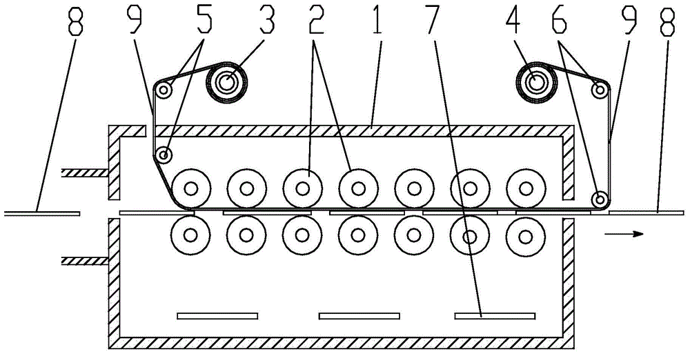
[0021] Combine below figure 1 , the present invention will be further described.

[0022] A double-roll continuous heat transfer device suitable for steel plates, comprising a heat box 1 and a paper release shaft 3 for heat transfer paper 9 arranged outside the heat box 1, which are respectively arranged at two opposite side ends of the heat box 1 There are steel plate imports and steel plate exits, and a steel plate clamping and conveying device arranged in the hot box 1 is also included. A heater 7 is arranged in the hot box 1, and a thermal insulation layer is arranged on the wall of the hot box 1.

[0023] From the entrance of the steel plate to the exit of the steel plate, there are many sets of heat transfer rollers 2; The gap between the steel plate 8 and the thermal transfer paper 9 and through which the steel plate 8 and the thermal transfer paper 9 pass is covered with a silicone layer on the outer circumferences of the upper and lower rotating shafts. On the uppe...


PUM


Abstract

The invention discloses a double-roller type continuous thermal transfer printing device applicable to steel plates. The double-roller type continuous thermal transfer printing device comprises a hot box and a heat transfer paper pay-off shaft arranged outside the hot box. The two opposite side faces of the hot box are provided with a steel plate inlet and a steel plate outlet respectively. A plurality of sets of heat transfer printing paired rollers are arranged from the steel plate inlet to the steel plate outlet. Each set of heat transfer printing paired rollers includes an upper rotary shaft and a lower rotary shaft, wherein the upper rotary shaft and the lower rotary shaft are arranged oppositely in an up-down mode. Gaps are formed between the upper rotary shafts and the lower rotary shafts and used for clamping the steel plates and heat transfer printing paper and enabling the steel plates and the heat transfer printing paper to pass through. According to the double-roller type continuous thermal transfer printing device, continuous operation is achieved through the paired extrusion rubber rollers, so the double-roller type continuous thermal transfer printing device is applicable to a single steel plate and continuous heat transfer printing of a steel plate strip; compared with traditional platform type printing equipment, the double-roller type continuous thermal transfer printing device greatly improves transfer printing efficiency.

Description

technical field [0001] The invention relates to a steel plate printing equipment, in particular to a pair-roller continuous thermal transfer device suitable for steel plates. Background technique [0002] At present, in order to beautify the steel plate, patterns are usually transferred on the surface of the plate by heat transfer printing. The method is to place the plate in a vacuum transfer bed, cover the surface of the plate with patterned transfer paper, and start the vacuum pump. Pump air, let the silicone skin of the transfer bed press tightly on the outside of the transfer paper, make the transfer paper close to the surface of the board, then push the transfer bed into the oven, heat at 1800C-200C for 3 -5 minutes, the pattern on the transfer paper will be transferred to the surface of the plate. Such thermal transfer equipment has at least the following disadvantages: ①The thermal transfer operation is discontinuous, requiring manual operation, opening and closing ...

Claims


Application Information

Patent Timeline
Patent Type & Authority Patents(China)
IPC IPC(8): B41F16/00
Inventor 马峰然
Owner 成都盛荣乐饰科技有限公司
Learn More