
A continuous thermal transfer process and special equipment suitable for single glass

A special equipment and thermal transfer printing technology, which is applied in transfer printing, rotary printing machine, printing, etc., can solve the problems of inability to realize continuous operation, poor transfer printing quality, complicated sealing device, etc., and achieve easy automatic operation and control, Effects of energy saving and equipment process simplification

Inactive Publication Date: 2016-05-18
殷殿荣 +1
View PDF10 Cites 0 Cited by
  • Summary
  • Abstract
  • Description
  • Claims
  • Application Information

AI Technical Summary

Problems solved by technology

Such thermal transfer equipment has at least the following disadvantages: ①The thermal transfer operation is discontinuous, requiring manual operation, opening and closing the frame back and forth, the process is cumbersome, the quality is not guaranteed, and the efficiency is extremely low; ②The thermal transfer equipment The normal use of the machine needs to add a sealing device at the opening and closing ends of the upper and lower racks, and the transfer bed is generally large, and the upper and lower racks are frequently opened and closed, the sealing device is very complicated, the sealing effect is poor, and it is easy to run out of air and transfer. Poor print quality
This patented technology proposes a complete operation plan for the operation mode of the platform, but it still cannot achieve continuous operation and is inefficient

Method used


Image

  • A continuous thermal transfer process and special equipment suitable for single glass
  • A continuous thermal transfer process and special equipment suitable for single glass

Examples


Embodiment Construction

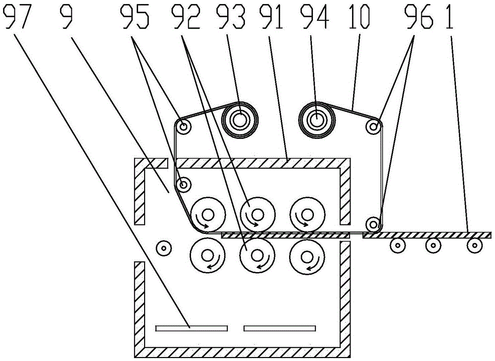
[0031]Referring to the accompanying drawings, the present invention is applicable to the continuous thermal transfer operation of a single piece of glass. The equipment of the present invention sequentially includes a feeding device 2 for flat glass 1, a cleaning device 3, an air drying device 4, and a transparent varnish processing device 5 according to the sequence of the flow operation. , heating surface drying device 6, solid color paint processing device 7, heating curing device 8 and roller type continuous thermal transfer device 9; cleaning device 3 is a spray cleaning machine, and a spray gun head is arranged above the flat glass 1, and the flat glass The bottom of 1 is the conveying roller 11; the air-drying device 4 includes a pair of hot air blowers relatively arranged on the upper and lower sides of the flat glass 1, and the lower part of the flat glass 1 is the conveying roller 11; the transparent paint processing device 5 and the solid color paint processing device...


PUM


Abstract

The invention discloses a continuous heat transfer printing technology suitable for a single glass block and a special device. Sheet glass sequentially passes through a cleaning device, an air drying device, a celluloid paint processing device, a heating and surface drying device, a solid color paint processing and coating device, a heating and solidifying device and a roller type continuous heat transfer printing device. The following technological processes are performed that firstly, the sheet glass is processed before being cleaned; secondly, the air drying treatment is performed on the sheet glass; thirdly, the upper surface of the sheet glass is sprayed with celluloid paint; fourthly, the heating and surface drying treatment is performed on the celluloid paint on the sheet glass in the heating and surface drying device; fifthly, the upper surface of the sheet glass is sprayed with solid color paint; sixthly, the heating and solidifying treatment is performed on the solid color paint on the sheet glass in the heating and solidifying device; seventhly, a heat transfer printing scroll is used for performing continuous heat transfer printing on the sheet glass. Compared with a traditional platform type printing device, the transfer printing efficiency is greatly improved, and meanwhile energy is greatly saved.

Description

technical field [0001] The invention relates to a flat glass printing process and equipment, in particular to a roller-type flat glass continuous thermal transfer method and device system suitable for a single piece of glass. Background technique [0002] At present, in order to beautify the glass plate, patterns are usually transferred on the surface of the plate by heat transfer printing. The method is to place the plate in a vacuum transfer bed, cover the surface of the plate with patterned transfer paper, and start the vacuum pump. Pump air, let the silicone skin of the transfer bed tightly press the outside of the transfer paper, make the transfer paper close to the surface of the board, then push the transfer bed into the oven and heat at 180°C-200°C After 3-5 minutes, the pattern on the transfer paper will be transferred to the surface of the board. Such thermal transfer equipment has at least the following disadvantages: ①The thermal transfer operation is discontinu...

Claims


Application Information

Patent Timeline
Patent Type & Authority Patents(China)
IPC IPC(8): B41F16/00B41F23/00
Inventor 马峰然
Owner 殷殿荣
Learn More