Liquid-crystalline medium, method for the stabilization thereof, and liquid-crystal display

A liquid crystal medium and medium technology, applied in chemical instruments and methods, liquid crystal materials, instruments, etc., can solve problems such as low contrast, insufficient service life, insufficient VHR, etc., and achieve good low temperature stability and low rotational viscosity.

Active Publication Date: 2014-06-04
MERCK PATENT GMBH
View PDF14 Cites 35 Cited by
  • Summary
  • Abstract
  • Description
  • Claims
  • Application Information

AI Technical Summary

Problems solved by technology

[0053] The deficiencies of the MLC displays disclosed so far are due to their relatively low contrast ratio, relatively high viewing angle

Method used


Image

  • Liquid-crystalline medium, method for the stabilization thereof, and liquid-crystal display
  • Liquid-crystalline medium, method for the stabilization thereof, and liquid-crystal display
  • Liquid-crystalline medium, method for the stabilization thereof, and liquid-crystal display

Examples


Embodiment 1

[0500] Examples 1.1.1 to 1.4.2 and Comparative Examples 1.1.0 to 1.4.0:

[0501] The following host mixture (H-1) was prepared and investigated.

[0502]

[0503] Note: t.b.d.: to be determined.

[0504] The mixture H-1 was first divided into four portions. Another compound of formula II was added to each of the quadruples, as indicated in the table below.

[0505]

[0506] All these mixtures were then again divided into three portions. The first copy is researched as it is. In addition, 200ppm of the following compound

[0507]

[0508] Or with 200ppm synthesis embodiment 1: the compound of (i.e. material embodiment 1)

[0509]

[0510] Add to the other two portions of the mixture. All mixtures were studied as described below.

[0511] First, the stability of the voltage retention ratio of the mixture (CM-1·n) was measured as it is. Four mixtures (CM-1-n, n ∈ {1; 2; 3; 4}), and four mixtures M-1-n-1, n ∈ {1; 2; 3; 4} containing the compound NOH ) an...

Embodiment 2

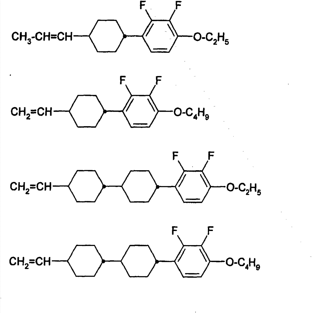
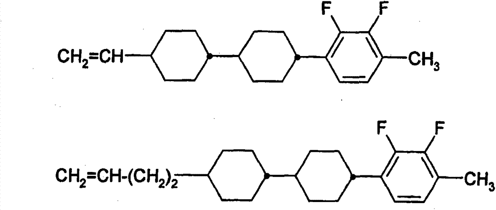
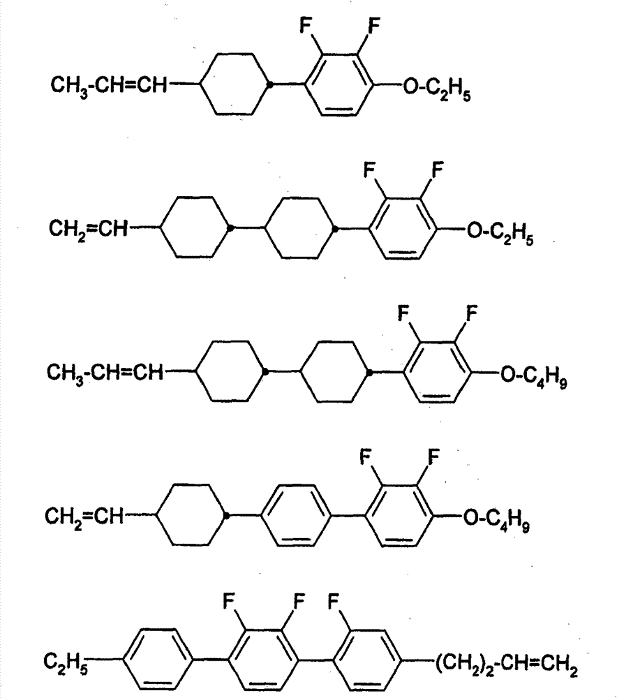
[0521] The following mixture (M-2) comprising 11.5% of the compound of formula II containing an alkenyl end group was prepared and studied.

[0522]

[0523] Mixture M-2 was divided into five portions and studied as described below.

[0524] The first aliquot of mixture M-2, as described in Example 1, was studied without addition of other compounds. In addition, the compound of 100ppm synthesis example 1: (i.e. material example 1)

[0525]

[0526] Or the compound of 50ppm synthetic embodiment 2: (being material embodiment 4)

[0527]

Embodiment 50

[0529]

[0530] or 250ppm compound "NOH"

[0531]

[0532] Added to the other four portions of mixture M-2. The resulting mixtures M-2-1 to M-2-4 were investigated as described in Example 1. The results are shown in the table below.

[0533] Table 2

[0534]

[0535] Note: I(1) * : the compound of Synthesis Example 1

[0536] I(2) * : the compound of Synthesis Example 2

[0537] I(3)*: the compound of Synthesis Example 7

[0538] I(N)*: compound NOH

[0539] All stabilizers used here, especially the compounds of the formula I, significantly improve the stability of the mixtures used. In particular, this applies to values ​​after exposure testing. Stabilizer I (3) here shows a particularly high activity and continues to show a high VHR until backlight irradiation. The use of mixture M-2 in LCDs is only possible to a limited extent without the use of stabilizers. The use of said stabilizers, especially compounds of formula I, leads to an increase in VHR to va...


PUM


Abstract

The invention relates to compounds of the formula I, and to a liquid-crystalline medium, preferably having a nematic phase and negative dielectric anisotropy, which comprises a) one or more compounds of the formula I and b) one or more compounds of the formula II in which the parameters have the respective meanings indicated in Claim 1, to the use thereof in an electro-optical display, particularly in an active-matrix display based on the VA, ECB, PALC, FFS or IPS effect, to displays of this type which contain a liquid-crystalline medium of this type, and to the use of the compounds of the formula I for the stabilization of a liquid-crystalline medium which comprises one or more compounds of the formula II.

Description

technical field [0001] The present invention relates to novel compounds, in particular for liquid-crystalline media, and also to the use of these liquid-crystalline media in liquid-crystal displays; Controlled birefringence) effect of the liquid crystal display. The liquid-crystalline media according to the invention are characterized in the displays according to the invention by particularly short response times at the same time as high voltage retention rates (VHR, or also abbreviated as HR). Background technique [0002] The principle of electrically controlled birefringence, the ECB effect or DAP (Deformation of Aligned Phase) effect, was first described in 1971 (M.F. Schieckel and K.Fahrenschon, "Deformation of nematic liquid crystals with vertical orientation in electrical fields", Appl. Phys. Lett .19(1971), 3912). These were followed by papers by J.F Kahn (Appl. Phys. Lett. 20 (1972), 1193) and G. Labrunie and J. Robert (J. Appl. Phys. 44 (1973), 4869). [0003] T...

Claims


Application Information

Patent Timeline
IPC IPC(8): C09K19/34C09K19/44C09K19/52G02F1/1333
CPCC09K19/42C09K19/54C09K19/3003C09K2019/301C09K19/12C09K2019/3009C09K2019/122C09K2019/3016C07D401/12C07D401/14G02F1/13
Inventor M·格贝尔E·巴伦R·福特D·保卢斯
Owner MERCK PATENT GMBH
Why Eureka
Try Eureka