Heat stake attachment feature

a technology of attachment feature and heat sink, which is applied in the direction of superstructure subunits, applications, fastening means, etc., can solve the problems of requiring some of the fastener design to be very small, the area between components such as b-pillars and appliqués, and the packaging space in vehicles is often very limited, so as to minimize the potential for a read condition, minimize the risk, and simplify the mold design

Active Publication Date: 2016-06-23
MAGNA INTERNATIONAL INC
View PDF5 Cites 9 Cited by
  • Summary
  • Abstract
  • Description
  • Claims
  • Application Information

AI Technical Summary

Benefits of technology

[0013]The present invention simplifies mold design, minimizes potential for a read condition, and provides a robust engagement for a winged clip type fastener in limited space.
[0014]It is an object of the invention to provide for attachment of the exterior ornamentation of an appliqué in a limited packaging space that is robust without introducing a read condition or breakage. It is another object of the invention to provide an attachment which is toolable in an injection molded part and which will meet a minimum pull off force without breakage while applied to the vehicle.
[0015]The present invention also provides design flexibility in term of secondary fastener orientation relative to adjacent features in the mold by means of simplified lifters, and provides a method of prevailing torque.
[0016]It is another object of the invention to minimize the risk associated with weak (small) tooling condition. It is another object of the invention to simplify the molding by minimizing lifter travel and lifter angle. It is yet another object of the invention to provide a prevailing torque on the primary fastener.
[0017]Principally, it is an objective of the invention to provide an attachment clip for extremely low profile vehicle ornamentation, high retention value given small size, heat stake retention, tolerance absorption, provide 360 degrees of float in the attachment for tolerance consideration, provide the option of limiting the float to two directions, and provide a simple and effective means of attaching the clip to a vehicle body ornamentation.

Problems solved by technology

The packaging space in vehicles is often very limited due to the number of components used to assemble the vehicle, the size of the vehicle, and the like.
Some of the area between components, such as a B-pillar and an appliqué, is very limited.
This requires some of the fastener designs to be very small.
Molded-in features, such as a doghouse, often cause a “read” condition on the show surface of a part due to differences in cooling temperatures between the feature and the substrate caused by differences in mass / volume of the resin.
The limited space also causes a tooling condition that is very fragile due to the reduced size.
A feature of the type described above has a minimum workable size which does not facilitate the doghouse having suitable strength.
The size of the part and the proximity of adjacent features limit the packaging space and travel of movable feature (lifters) in the mold.
Current designs include a molded “boss” which is threadable, but tends to cause a read condition as discussed above, and also tends to break, increasing scrap during manufacturing.
Another design has separately molded doghouses with adhesive backing applied to the part, which designs also lack suitable strength and do not meet space limitations in current low profile designs.
However, none of these designs overcome the aforementioned problems.
In another, a typical molded integral doghouse with a standard plastic winged clip is on the back side of a molded part and will generally produce visible defects on the finished side of the part.
The low profile packaging space also does not provide for a robust tooling condition for a conventional molded doghouse.
Other design requirements are necessitating very low profile exterior ornamentations that present extremely low profile attachment challenges in order to attach to a component body.
The packaging space provided in low profile designs is also not toolable from an injection molding perspective.
Current body attachments do not provide low profile designs that meet all of the aforementioned criteria simultaneously.

Method used


Image

  • Heat stake attachment feature
  • Heat stake attachment feature
  • Heat stake attachment feature

Examples


Embodiment Construction

[0034]The following description of the preferred embodiment(s) is merely exemplary in nature and is in no way intended to limit the invention, its application, or uses.

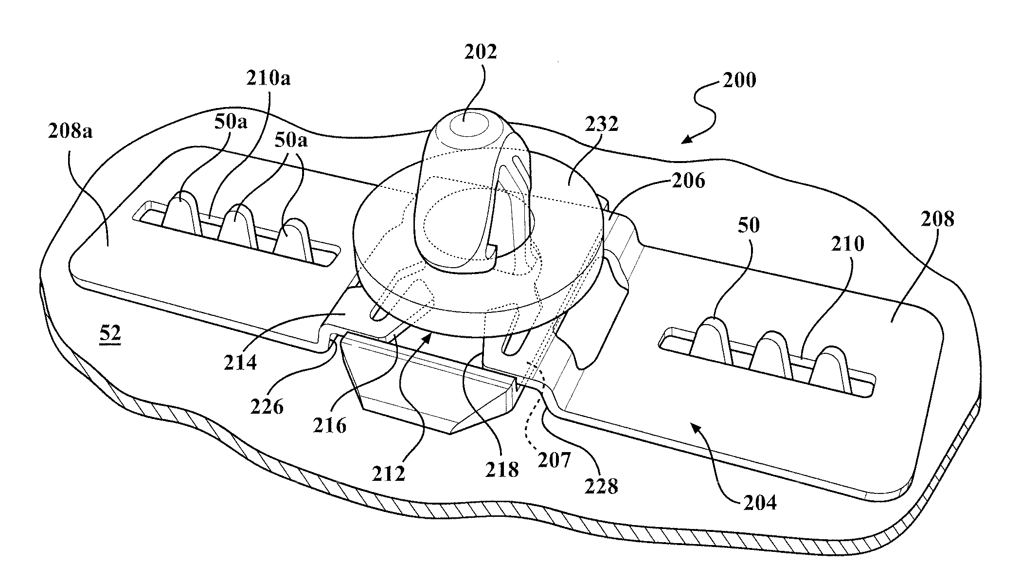
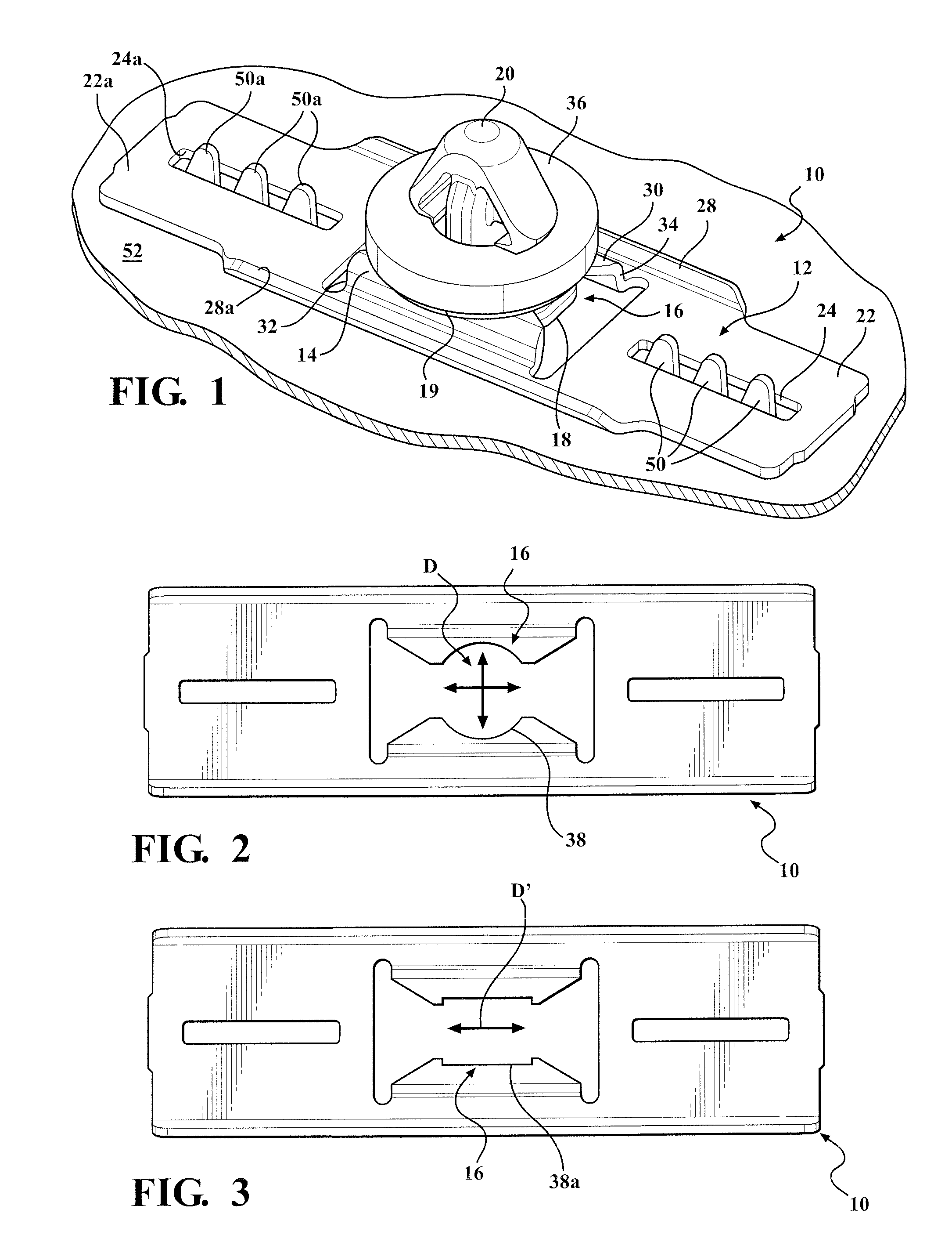
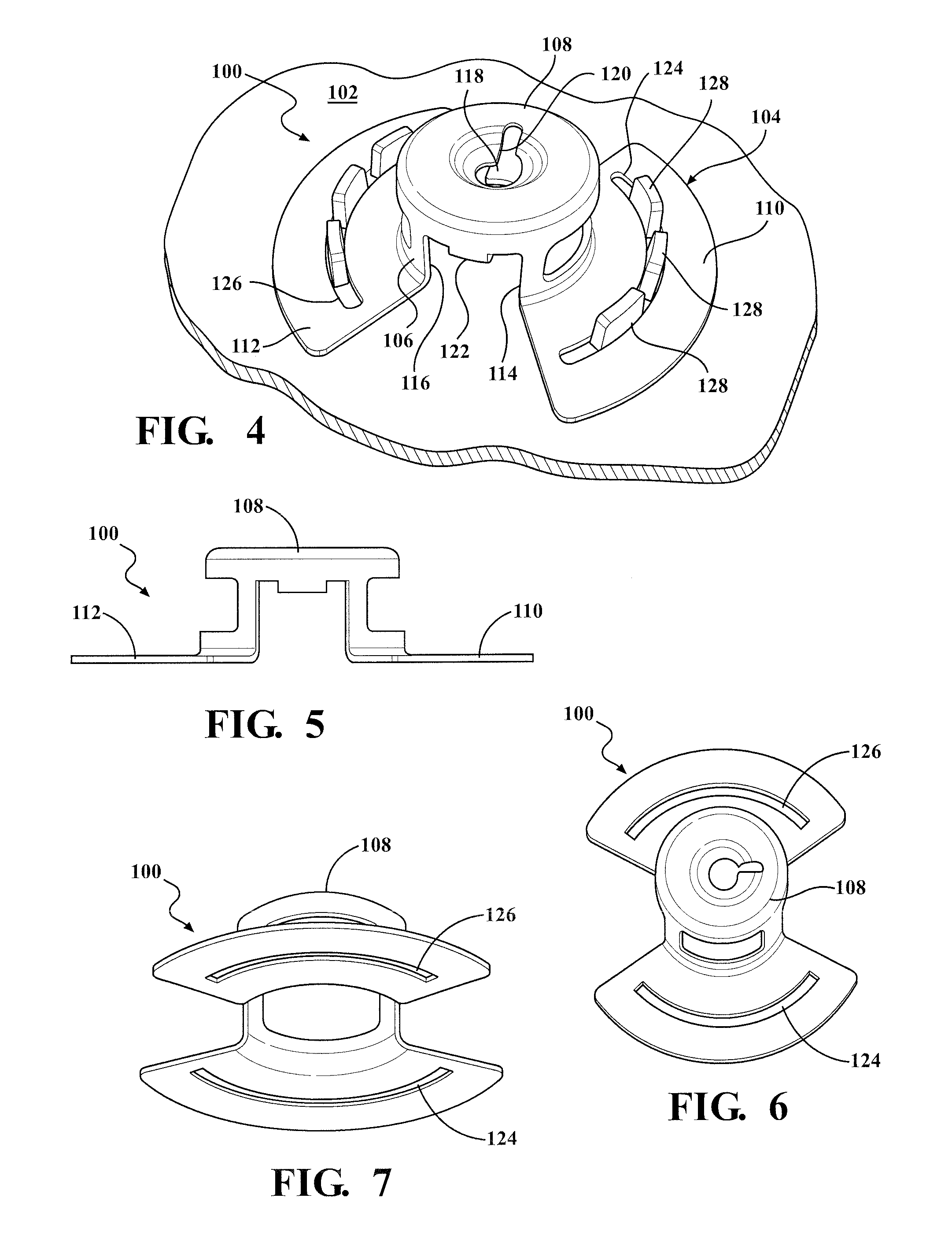
[0035]There is generally provided an assembly including a spring steel carrier with heat stake features and a winged clip connectable to the carrier. The invention provides a low profile permitting its use in extremely limited packaging space. The invention also provides an opening in the formed base to accept a molded plastic winged clip to provide an attachment means to the vehicle and maintain predetermined ergonomic application requirements depending upon the application. Alternatively, there is generally provided a heat staked radial clip. Preferably, there is provided a nylon clip coupled to a low profile metal carrier with clip float features and / or nylon clip float limiters for predetermined amount and direction of float. The embodiments all incorporate a heat stake feature with superior benefits over other de...


PUM

PropertyMeasurementUnit
yield strengthaaaaaaaaaa

Abstract

A retainer for limited space attachment of a vehicle part with a class A surface to a vehicle. The retainer has a low profile portion and also an attachment base operable for being connected to heat stake ribs of the vehicle part. The attachment base includes at least one attachment aperture to provide attachment with the heat stake ribs. There is provided desired degrees of clip float and/or two-way limited clip float providing desired free movement of the clip when desired.

Description

CROSS-REFERENCE TO RELATED APPLICATIONS[0001]This application claims the benefit of U.S. Provisional Application No. 62 / 093,062, filed Dec. 17, 2014. The disclosure of the above application is incorporated herein by reference.FIELD OF THE INVENTION[0002]The present invention relates to a retainer assembly and method for providing a secure connection between a first attachable part such as an appliqué and the pillar or other component part of an automobile.BACKGROUND OF THE INVENTION[0003]The components of an automobile are connected together in many different ways. One type of connection uses a fastener, such as a bolt or screw.[0004]The packaging space in vehicles is often very limited due to the number of components used to assemble the vehicle, the size of the vehicle, and the like. Some of the area between components, such as a B-pillar and an appliqué, is very limited. This requires some of the fastener designs to be very small. Typically, one type of connector used for retaini...

Claims


Application Information

Patent Timeline
Patent Type & Authority Applications(United States)
IPC IPC(8): B60R13/02F16B2/22
CPCF16B2/22B60R13/0206
Inventor BACHELDER, THEODORE J.GIGNILLIAT, MICHAEL S.
Owner MAGNA INTERNATIONAL INC
Why Eureka
Try Eureka