Device for eliminating movement of bridge end track ballast of large-span bridge with ballast tracks

A technology for long-span bridges and tracks, applied in bridges, bridge parts, bridge construction, etc., can solve problems such as difficulty in maintaining the geometric shape of the rail telescopic adjuster, difficulty in maintaining the geometric shape of the adjuster, troublesome maintenance and repair of the public works department, etc. Achieve the effect of reducing maintenance and repair workload, simple structure and low price

Inactive Publication Date: 2014-06-04
CHINA RAILWAY SIYUAN SURVEY & DESIGN GRP
View PDF0 Cites 5 Cited by
  • Summary
  • Abstract
  • Description
  • Claims
  • Application Information

AI Technical Summary

Problems solved by technology

When laying the rail telescopic adjuster at the end of a long-span bridge, since the rail telescopic adjuster is the weak link of the seamless line, under the action of the expansion and contraction of the bridge beam body and the repeated load of the locomotive, large gaps will occur between the beam and the rail at the telescopic adjuster. The relative displacement of the ballast at the beam joint is easy to move, resulting in uneven ballast at the rail telescopic adjuster, and there will be defects such as vertical unevenness of the rail and difficulty in maintaining the geometric shape of the adjuster.
Therefore, the previous method of installing rail telescopic regulators at the seams of long-span bridges with ballasted tracks is unreasonable. The movement of ballast will cause vertical irregularity of the rail at the beam end, and it is difficult to maintain the geometric shape of the rail telescopic regulators. and other diseases will even be critical to the safety of the train when it is serious, and it has also caused a lot of trouble to the maintenance and repair of the public works department. Therefore, it is necessary to improve the existing technology

Method used


Image

  • Device for eliminating movement of bridge end track ballast of large-span bridge with ballast tracks
  • Device for eliminating movement of bridge end track ballast of large-span bridge with ballast tracks

Examples


Embodiment Construction

[0016] The present invention will be further described in detail below in conjunction with the accompanying drawings and specific embodiments to facilitate a clear understanding of the present invention, but they do not limit the present invention.

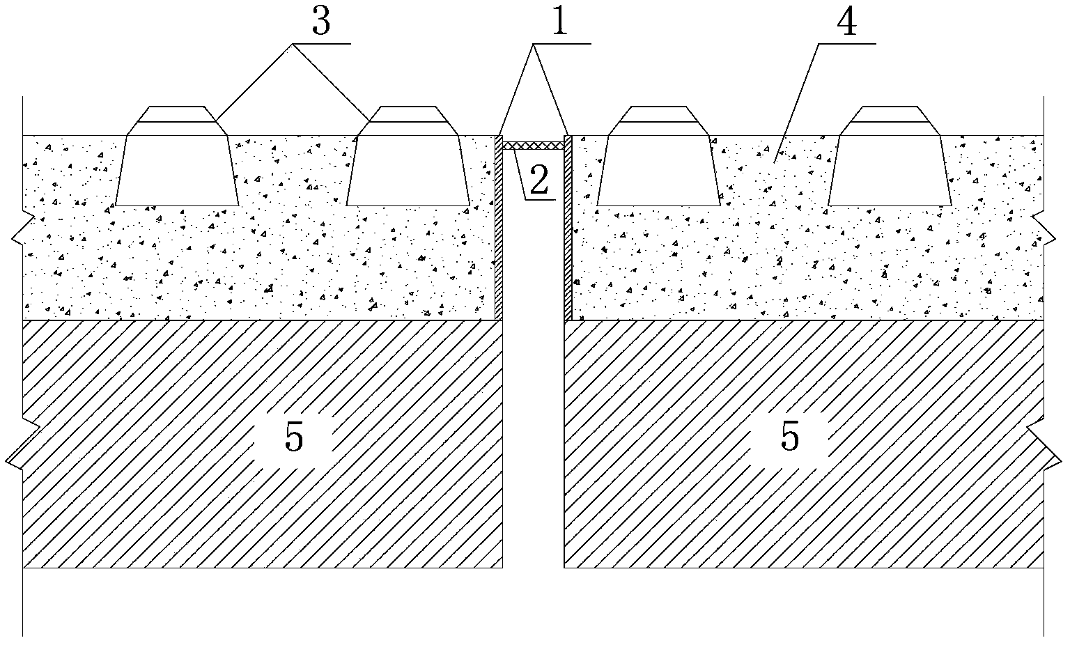
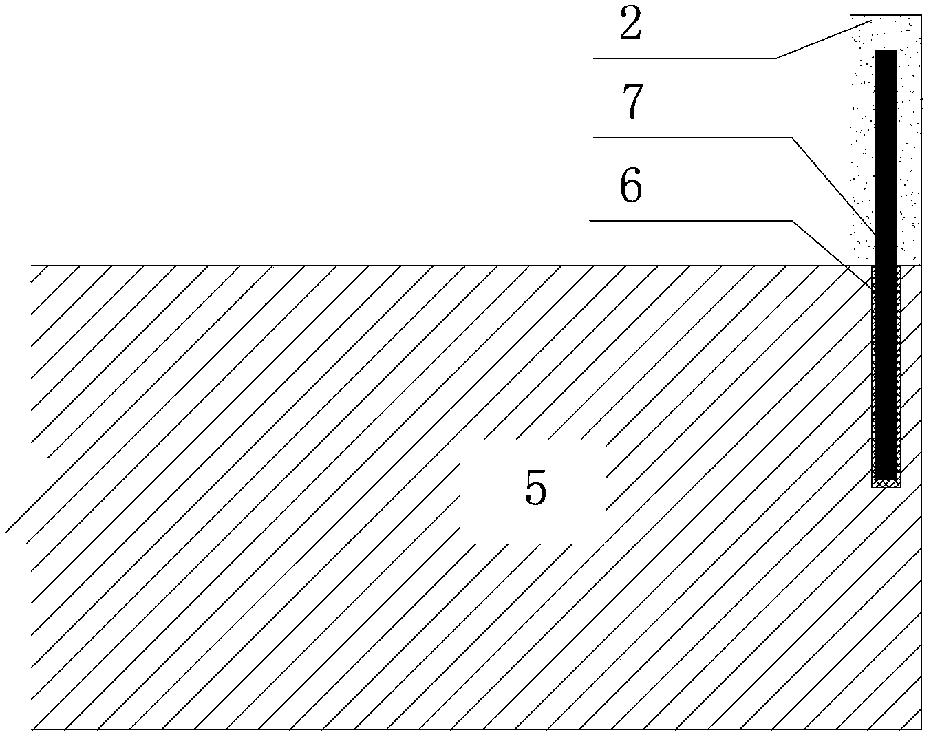
[0017] Such as figure 1 , figure 2 As shown, a device for solving ballast movement at the end of a long-span bridge with ballast track, it includes a ballast 4 arranged on a bridge girder body 5, a railway track 3 is arranged on the ballast 4, and along the railway track 3 The side of the ballast 4 on the bridge beam body 5 is provided with a ballast retaining plate 1. In this embodiment, the bridge beam body 5 is a concrete structure, and the ballast retaining plate 1 is a reinforced concrete structure. 6 and steel bars 7 are combined with the bridge girder body 5 as an integrated structure. An anti-fall structure 2 is provided between adjacent ballast retaining plates 1. The anti-fall structure 2 can expand and contract freel...


PUM


Abstract

The invention discloses a device for eliminating movement of bridge end track ballast of a large-span bridge with ballast tracks. The device comprises the track ballast arranged on a bridge girder body, wherein the railway tracks are arranged on the track ballast, ballast blocking plates are arranged on the side faces of the track ballast on the bridge girder body in the direction of the railway tracks, the ballast blocking plates and the bridge girder body are of an integrated structure, a falling preventing structure is arranged between every two adjacent ballast blocking plates, and the falling preventing structures are connected with the ballast blocking plates through hooks. According to the device for eliminating movement of the bridge end track ballast of the large-span bridge with the ballast tracks, due to the fact that the ballast blocking plates are arranged, the problem that in the prior art, track ballast in girder joints protrudes or sinks is solved, the damage phenomena that due to movement of the track ballast, steel rails are irregular in the vertical direction, and the geometry position of a steel rail expansion adjuster cannot be easily kept can be effectively prevented, the workload of maintenance is remarkably reduced, and the device has the advantages that structure machining is easy, sources are wide, the cost is low, and quality is reliable.

Description

technical field [0001] The invention relates to the technical field of railway tracks, in particular to a device for solving ballast movement at the end of a long-span bridge on a ballasted track. Background technique [0002] The ballast is a granular structure. When the ballast track is laid on the long-span bridge, in order to prevent the ballast from falling off the beam end caused by the expansion and contraction of the bridge, the measures of setting the cover plate at the beam joint are generally adopted at present. After the cover plate is set, the ballast is prone to shifting regardless of whether the rail telescopic regulator is laid at the end of the long-span bridge, causing the rail to be uneven. When no rail telescopic regulator is installed at the end of the long-span bridge, the elongation of the high-temperature beam body in summer will cause the ballast to arch at the beam joint, and the shortening of the beam body at low temperature in winter will cause th...

Claims


Application Information

Patent Timeline
Patent Type & Authority Applications(China)
IPC IPC(8): E01D19/12
Inventor 戴金松孙立李秋义王森荣杨艳丽李平卓李志红
Owner CHINA RAILWAY SIYUAN SURVEY & DESIGN GRP
Why Eureka
Try Eureka