Stacked composite ballastless rail system for rail transportation

A technology for rail transit and ballastless track, which is applied in the field of stacked composite ballastless track system for rail transit, can solve the problems of inability to perform maintenance and replacement, replacement, difficulty in maintenance, high vibration and noise, etc., so as to reduce maintenance Maintenance workload, ensure normal operation, good elasticity

Pending Publication Date: 2018-07-13
青岛安平轨道工程技术咨询有限公司
View PDF11 Cites 2 Cited by
  • Summary
  • Abstract
  • Description
  • Claims
  • Application Information

AI Technical Summary

Problems solved by technology

[0002] In the field of rail transit using the wheel-rail system, there are two types of existing ballastless track structures, one is the slab ballastless track, and the other is the sleeper embedded ballastless track. Both ballastless track structures are Including rails, fasteners and ballastless track bed, etc. After the rails and fasteners transmit the train dynamics to the ballastless track bed, the concrete track slab and concrete sleepers are the main load-bearing components and the key components of the ballastless track bed. It is a reinforced concrete structure. Once such a structure is damaged, it is very difficult to replace and repair it. This is especially true for the sleeper-embedded ballastless track. Since the concrete sleeper is directly embedded in the concrete track bed, apart from demolition and reconstruction It is impossible to carry out maintenance and replacement. In addition, the traditional ballastless ballast bed adopts reinforced concrete structure, which leads to a relatively high rigidity of the track, and the vibration and noise caused by train operation are relatively large. Measures for reducing vibration and noise of the track have to be taken in areas sensitive to vibration and noise. lead to increased investment

Method used


Image

  • Stacked composite ballastless rail system for rail transportation
  • Stacked composite ballastless rail system for rail transportation
  • Stacked composite ballastless rail system for rail transportation

Examples


Embodiment Construction

[0015] In order to deepen the understanding of the present invention, the present invention will be further described below in conjunction with the examples, which are only used to explain the present invention, and do not constitute a limitation to the protection scope of the present invention.

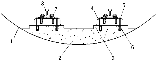
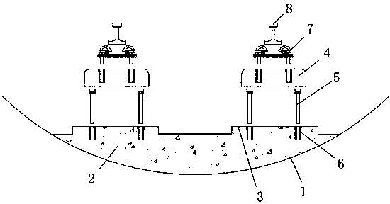
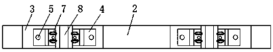
[0016] according to figure 1 , 2 As shown in , 3, this embodiment provides a stacked composite ballastless track system for rail transit, including an off-line foundation 1, a reinforced concrete ballast bed 2, a reinforced concrete buttress 3, a composite sleeper 4, and sleeper anchor bolts 5 , anchor bolt sleeve 6, fastener system 7, steel rail 8, the top of the underground foundation 1 is laid with a reinforced concrete ballast bed 2, and the top of the reinforced concrete ballast bed 2 is evenly arranged with reinforced concrete buttresses 3 according to the fastener node spacing, the described Composite sleepers 4 are provided on the top of the reinforced concrete pier 3, and t...


PUM


Abstract

The invention discloses a stacked composite ballastless rail system for rail transportation. The stacked composite ballastless rail system comprises an off-line foundation, a reinforced concrete ballast bed, reinforced concrete buttresses, composite sleepers, sleeper anchoring bolts, anchoring bolt sleeves, a fastener system and a steel rail, the reinforced concrete ballast bed is laid at the topof the off-line foundation, the reinforced concrete buttresses are uniformly arranged at the top of the reinforced concrete ballast bed according to fastener node spacing, and the composite sleepers are arranged at the tops of all the reinforced concrete buttresses. By means of the stacked composite ballastless rail system for the rail transportation, a stacked structure replaces an embedded structure, that is, the composite sleepers are stacked on the reinforced concrete buttresses, the embedded structure of traditional reinforced concrete sleepers is replaced, key parts are easy to replace,and the composite sleepers can be made of polymer materials like polyurethane, rubber and rubber plastic.

Description

technical field [0001] The invention relates to the technical field of urban rail transit, in particular to a stacked composite ballastless track system for rail transit. Background technique [0002] In the field of rail transit using the wheel-rail system, there are two types of existing ballastless track structures, one is the slab ballastless track, and the other is the sleeper embedded ballastless track. Both ballastless track structures are Including rails, fasteners and ballastless track bed, etc. After the rails and fasteners transmit the train dynamics to the ballastless track bed, the concrete track slab and concrete sleepers are the main load-bearing components and the key components of the ballastless track bed. It is a reinforced concrete structure. Once such a structure is damaged, it is very difficult to replace and repair it. This is especially true for the sleeper-embedded ballastless track. Since the concrete sleeper is directly embedded in the concrete tra...

Claims


Application Information

Patent Timeline
Patent Type & Authority Applications(China)
IPC IPC(8): E01B1/00E01B3/44
CPCE01B1/002E01B1/005E01B3/44E01B2204/09
Inventor 李爱基
Owner 青岛安平轨道工程技术咨询有限公司
Why Eureka
Try Eureka