
High-speed rail bridge wind shielding structure vertical column

A high-speed railway and column technology, applied in bridges, bridge parts, bridge construction, etc., can solve the problems of easy overturning, stiffness, stress, and connection reliability that cannot meet the requirements of high-speed railways, and achieve the purpose of increasing the bending arm , construction difficulty and workload reduction, and the effect of solving fatigue problems

Inactive Publication Date: 2015-03-11
CHINA RAILWAY FIRST SURVEY & DESIGN INST GRP
View PDF6 Cites 2 Cited by
  • Summary
  • Abstract
  • Description
  • Claims
  • Application Information

AI Technical Summary

Problems solved by technology

[0003] Due to the high speed and light axle load, high-speed railway trains are more likely to overturn under the action of strong lateral winds; at the same time, the aerodynamic force of trains is much greater than that of ordinary-speed railway trains. Currently, the stiffness, stress and connection of ordinary-speed bridge windshield structure column structures are reliable. None of them can meet the requirements of high-speed railway

Method used


Image

  • High-speed rail bridge wind shielding structure vertical column
  • High-speed rail bridge wind shielding structure vertical column
  • High-speed rail bridge wind shielding structure vertical column

Examples


Embodiment Construction

[0032] The present invention will be described in detail below in combination with specific embodiments.

[0033] The invention relates to a column of a high-speed railway bridge windshield structure, which is installed on the windward side of the bridge girder, and is arranged on one or both sides along the longitudinal line, with a longitudinal distance of 1.6-2.5m, and a windshield with holes is fixed between adjacent columns , forming a windshield structure.

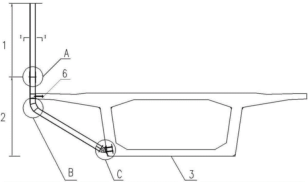
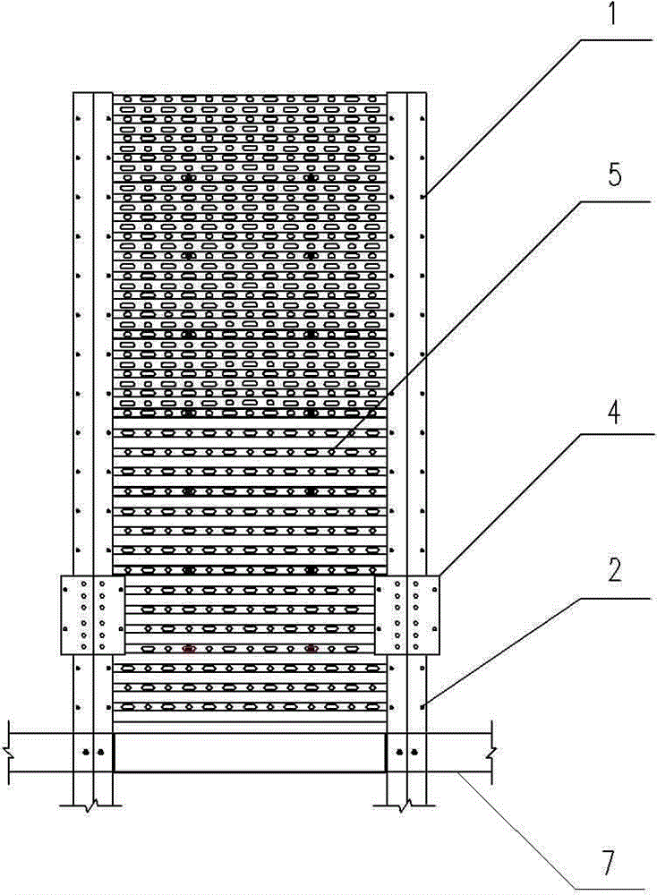
[0034] Controlled by the train limit, the column above the bridge deck adopts a straight line form, called the straight section column 1, and below the bridge deck, according to the cantilever length of the beam body flange and the anchorage position of the web, it is set in the form of a local arc L-shaped column, called the bent section column 2. The straight column 1 and the curved column 2 are spliced ​​up and down and fixed. The straight column 1 is a rolled H-shaped steel, and the curved column 2 is a welded a...


PUM


Abstract

The invention relates to a high-speed rail bridge wind shielding structure vertical column. The existing ordinary-speed rail bridge wind shielding measures cannot satisfy a windproof requirement of a high-speed rail bridge in a strong wind area. The high-speed rail bridge wind shielding structure vertical column comprise a straight-section vertical column and a bending-section vertical column which are vertically fixed by splicing; the straight-section vertical column and the bending-section vertical column are provided with bolt holes which are used for fixing wind shielding plates; the upper portion of the bending-section vertical column is vertical and the lower portion bends towards a central line of a beam body; the upper portion vertical portion of the bending-section vertical column is fixed at a flange of the beam body and the bottom end is fixed on a box beam web; a vertical column splicing seam of the straight-section vertical column and the bending-section vertical column is arranged above a bridge surface; the external side is provided with a vertical column splicing plate; a vertical column connecting bolt is arranged on the vertical column splicing plate to enable the straight-section vertical column and the bending-section vertical column to be vertically connected with fixed. According to the high-speed rail bridge wind shielding structure vertical column, the cross wind function acting on a train body is changed through a wind shielding structure under the premise that the safety of the bridge structure and the wind shielding structure is satisfied, the critical wind speed of the train safe operation is improved, the train operation stability is increased, and the operation fault is reduced.

Description

technical field [0001] The invention belongs to the technical field of high-speed railway windproofing, and in particular relates to a column of a high-speed railway bridge windproofing structure. Background technique [0002] For railways located in windy areas, trains are often overturned by strong winds, which has brought huge economic losses and serious social impacts to the transportation and production of railways. At present, my country has only set up wind-shielding structures for individual ordinary-speed railway bridges in the windy areas of Lanxin Railway and Nanjiang Railway. Use Q345qD steel. The upright column of the existing general-speed bridge windshield structure is connected with the upper ballast wall of the conjoined flange by bolts, and the distance between the bolts at the bottom of the upright column is small, and the bolts are prone to failure due to fatigue. [0003] Due to the high speed and light axle load, high-speed railway trains are more lik...

Claims


Application Information

Patent Timeline
IPC IPC(8): E01D19/00E01D19/10
CPCE01D19/00E01F7/025
Inventor 何涛张鹏赵会东徐永利吴少海俞萍
Owner CHINA RAILWAY FIRST SURVEY & DESIGN INST GRP
Learn More