Mine draw shaft safety protection structure

A technology of safety protection and well sliding, applied in safety devices, mining equipment, earth-moving drilling, etc., can solve problems such as hidden dangers in mine maintenance, safety platforms are easily collapsed, and safety platforms are unreliable, etc. The effect of saving maintenance time and enhancing reliability

Inactive Publication Date: 2014-06-04
WUHAN IRON & STEEL (GROUP) CORP
0 Cites 4 Cited by

AI-Extracted Technical Summary

Problems solved by technology

The vibrating ore-drawing machine is an important equipment for the production of the chute, and it is installed at the lower part of the chute. The maintenance of the vibrating ore-drawing machine is a safety hazard in mine maintenance.
At present, the safety protection measure for overhauling the vibratory ore-drawing machine is to build a safety platform above the eyebrow line of the chute. During the construction of the safety platfor...

Abstract

The invention discloses a mine draw shaft safety protection structure. The mine draw shaft safety protection structure comprises a fixed support arranged above the outer side of a draw shaft opening. An oil cylinder support is arranged on the draw shaft opening below the fixed support. The fixed support is hinged to the head end of a main beam. An upper oil cylinder is hinged between the front section of the main beam and the oil cylinder support. The rear section of the main beam abuts against the top edge of the draw shaft opening and stretches into the draw shaft opening. The tail end of the main beam is hinged to the head end of an auxiliary beam. The tail end of the auxiliary beam abuts against the bottom surface of the draw shaft opening. A lower oil cylinder is hinged between the auxiliary beam and the rear section of the main beam. An upper cover plate is arranged above the rear section of the main beam. A rear cover plate is arranged on the inner side of the auxiliary beam. The mine draw shaft safety protection structure can be installed on the draw shaft opening, workers do not need to enter a draw shaft to conduct operation, potential safety hazards are avoided, and safety protection is provided for maintenance of a draw shaft ore drawing device; multi-point fixation is adopted, and therefore stability and stability of the whole structure are improved; the mine draw shaft safety protection structure is convenient and quick to use, a great amount of maintenance time can be saved, and labor intensity is relieved.

Application Domain

Safety equipments

Technology Topic

WellheadEngineering +3

Image

  • Mine draw shaft safety protection structure
  • Mine draw shaft safety protection structure
  • Mine draw shaft safety protection structure

Examples

  • Experimental program(1)

Example Embodiment

[0016] The present invention will be further described in detail below in conjunction with the accompanying drawings and specific embodiments to facilitate a clearer understanding of the present invention, but they do not limit the present invention.
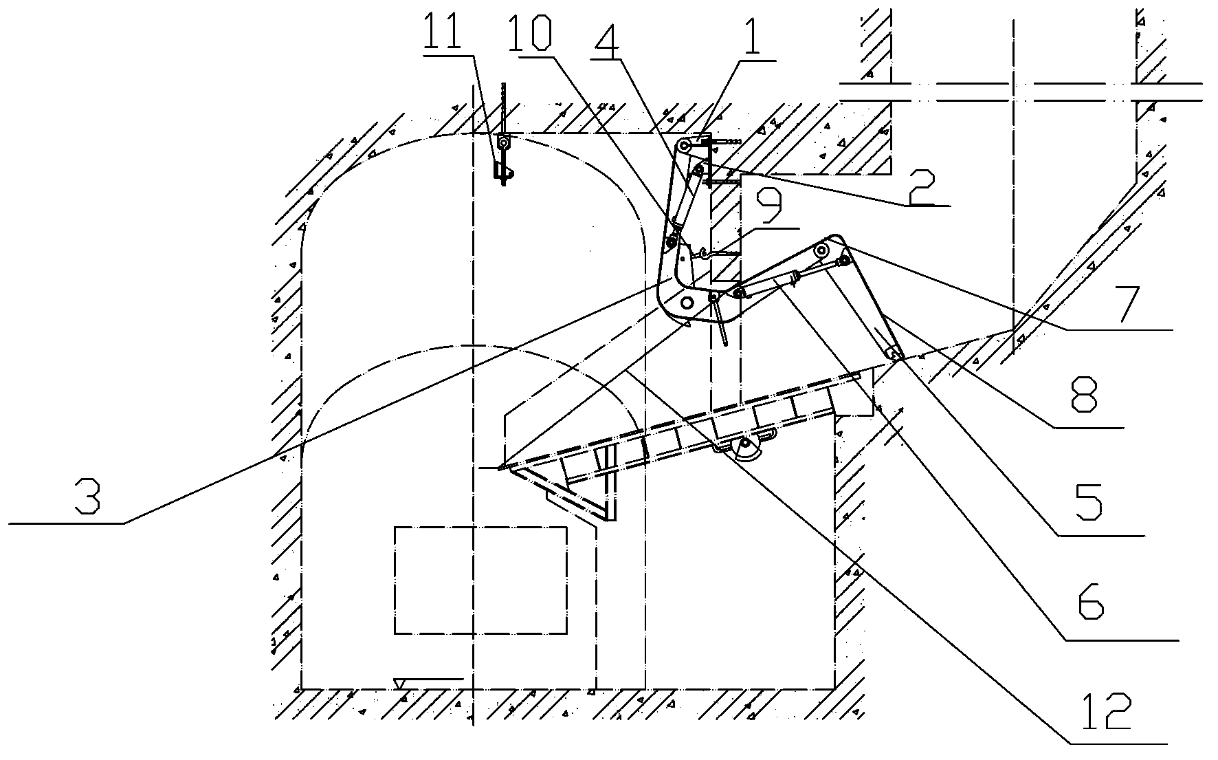
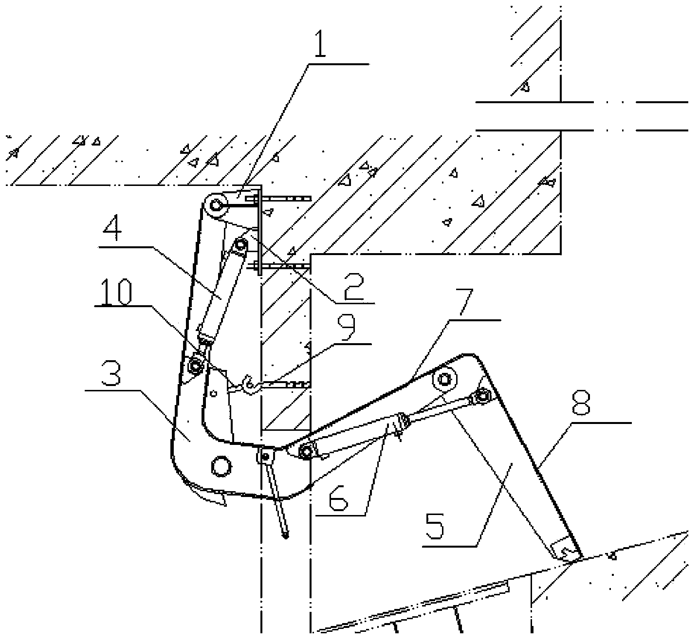
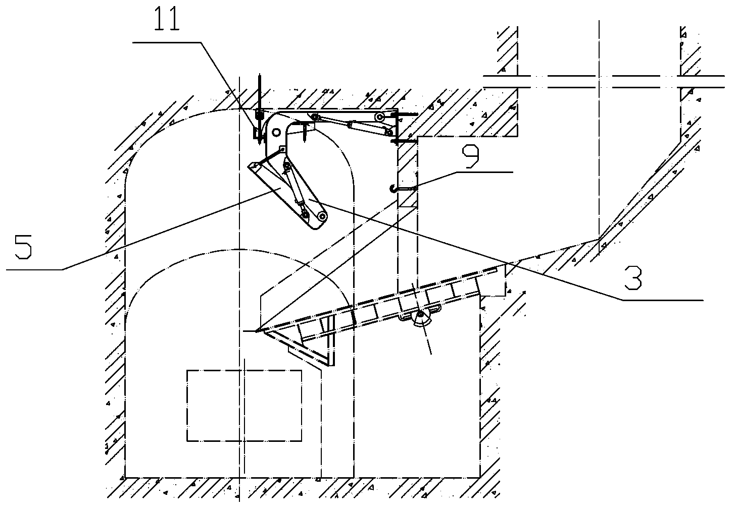
[0017] Such as figure 1 , figure 2 As shown, the present invention includes a fixed support 1 arranged on the well wall above the outer side of the chute head, and an oil cylinder support 2 is provided on the chute below the fixed support 1 and the fixed support 1 and the main beam 3 The head end is hinged. The main beam 3 is bent as a whole, preferably a C-shaped main beam. The front section of the main beam 3 extends from the top of the outside of the chute to the entrance of the chute, and the front section of the main beam 3 is hinged with the cylinder support 2. There is an upper cylinder 4, and the rear section of the main beam 3 abuts against the top edge of the well head and extends obliquely upward into the well head, that is, the rear section of the main beam 3 is on the eyebrow line of the well head, and the main beam 3 The end of the auxiliary beam 5 is hinged to the head end of the auxiliary beam 5, and the end of the auxiliary beam 5 abuts the bottom panel of the chute head. The auxiliary beam 5 is a straight beam. To prevent rotation, the included angle between the auxiliary beam 5 and the bottom surface of the chute is less than 80° That is, the included angle between the auxiliary beam 5 and the floor of the vibrating ore drawing machine is less than 80°, preferably 77°. The rear section of the main beam 3 is connected to the auxiliary beam 5 in a knuckle shape, a lower cylinder 6 is hinged therebetween, an upper cover 7 is provided above the rear section of the main beam 3, and the inner side of the auxiliary beam 5 is provided There is a rear cover plate 8, that is, the cover plate faces the direction of the well. The upper cover plate 7 and the rear cover plate 8 can be rectangular metal plates, which are welded to the main beam 3 and the auxiliary beam 5, respectively, to prevent smashing in the chute The ore from the ore enters the vibratory ore drawing machine 12 under maintenance to avoid safety accidents. The main beam is preferably a box beam, and the secondary beam is preferably a trough beam. In addition, a lower hook 9 is provided on the well wall of the chute under the cylinder support 2, and a connecting ring 10 is provided on the front section of the main beam 3, and the connecting ring 10 is buckled and connected with the lower hook 9 to connect The main beam 3 is completely and firmly fixed on the chute wall. According to operation needs, multiple groups of this safety protection structure can be combined to form a safety protection shed.
[0018] The safety protection structure can be folded and stretched freely. When not in use, it can be folded and hung on the upper hook 11 with a pawl on the top plate. There is no need for frequent disassembly and assembly. It also solves the problem of avoiding guns. At this time, the front section of the main beam 3 The connecting ring 10 is removed from the lower hook 9 (such as image 3 Shown).

PUM

no PUM

Description & Claims & Application Information

We can also present the details of the Description, Claims and Application information to help users get a comprehensive understanding of the technical details of the patent, such as background art, summary of invention, brief description of drawings, description of embodiments, and other original content. On the other hand, users can also determine the specific scope of protection of the technology through the list of claims; as well as understand the changes in the life cycle of the technology with the presentation of the patent timeline. Login to view more.

Similar technology patents

Control system and method for motor vehicles

InactiveUS20040084002A1improve reliabilityspeed and stability
Owner:TOYOTA JIDOSHA KK

Installation management method, server and terminal for application program

InactiveCN102446106Aprevent crackingImprove reliability
Owner:LENOVO (BEIJING) CO LTD

Forest fireproof monitoring and patrolling system

Owner:内蒙古亨利新技术工程股份有限公司

Unmanned aerial vehicle flight control system having multisensor redundant backup

ActiveCN105867414AIncrease flight control weight and costImprove reliability
Owner:ZHEJIANG UNIV

Classification and recommendation of technical efficacy words

  • Improve reliability
  • Improve stability

Multiple branch predictions

ActiveUS20050268075A1improve reliabilityfacilitate availability
Owner:ORACLE INT CORP

Implantable lead

ActiveUS20100137928A1good flexibility , fatigue resistance and flex lifeimprove reliability
Owner:WL GORE & ASSOC INC
Why Eureka
Try Eureka