Novel counter-rotating fan

A ventilator, rotary technology, applied in the field of new counter-rotary ventilators, can solve the problems of restricting development, weakening the ability of rotary technology to do work on airflow, etc., to reduce input costs, reduce structural complexity, and increase service life Effect

Inactive Publication Date: 2014-06-04
胡小全 +1
View PDF5 Cites 8 Cited by
  • Summary
  • Abstract
  • Description
  • Claims
  • Application Information

AI Technical Summary

Problems solved by technology

[0005] Most of the existing counter-rotating fans use two motors to drive the two rotor blades to rotate, and usually the two rotor blades rotate in opposite directions, and there is a problem of mutual restraint in aerodynamic coupling, which is mainly because when designing the blades It is necessary to consider not only the work done for the airflow, but also the coupling of the airflow passing through the rotor blades and the next-stage rotor blades, so this limits the development of counter-rotation technology in civil fans.
[0006] After consulting the data, it is found that there is no fan that uses a single motor to drive the counter-rotating blades in the market today.
In addition, in the counter-rotating fan that has been designed and produced and uses two motors to drive the counter-rotating blades, there is no mechanism between the two rows of rotor blades to guide the airflow, which weakens the ability of the counter-rotating technology to do work on the airflow. ability

Method used


Image

  • Novel counter-rotating fan
  • Novel counter-rotating fan
  • Novel counter-rotating fan

Examples


Embodiment Construction

[0030] The present invention will be further described below in conjunction with the accompanying drawings.

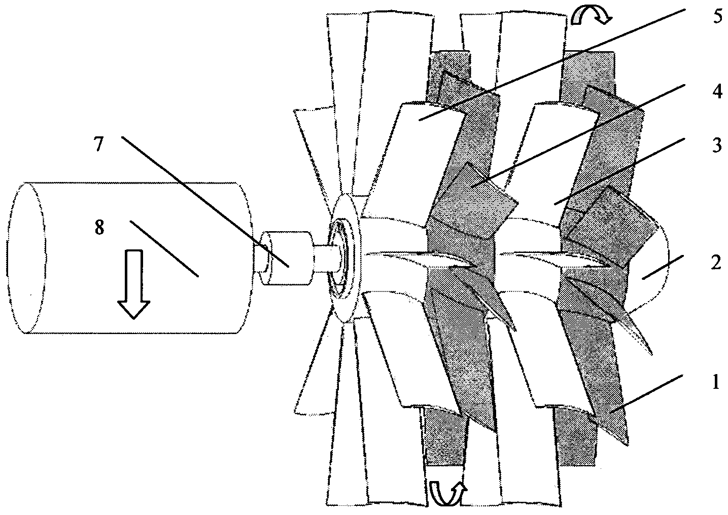
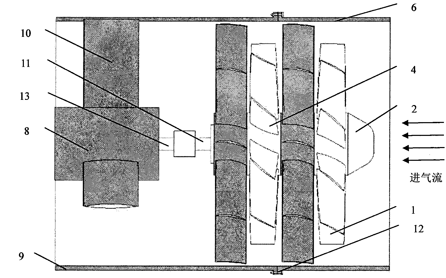
[0031] The new counter-rotating fan is mainly used in mines, large factories, tunnels, cooling towers, ships and buildings where ventilation, dust removal and cooling are required, especially where high-pressure airflow is required.

[0032] For the new counter-rotating fan, according to the design drawings, the manufacturer of this kind of counter-rotating fan will install it according to the following steps after producing all the parts:

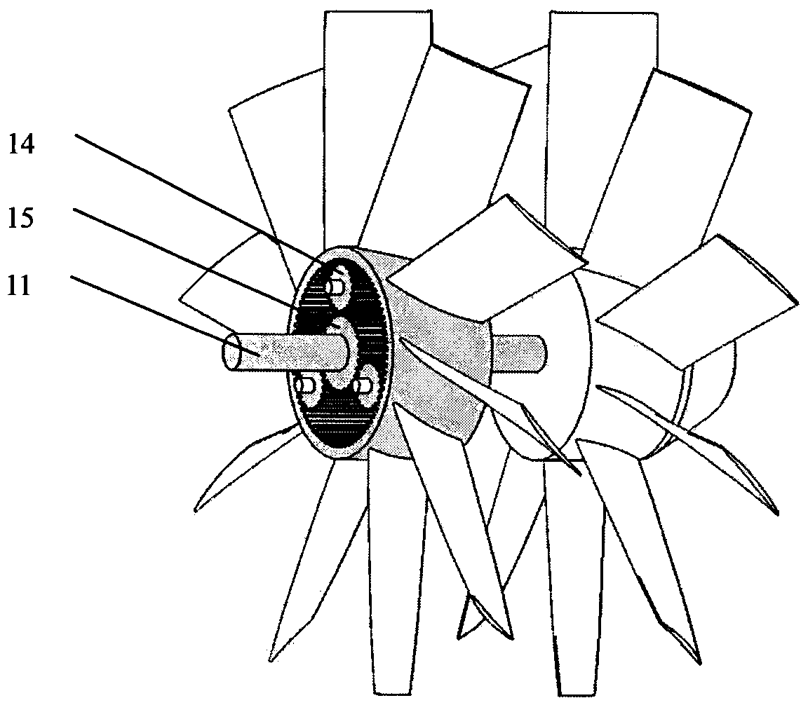
[0033] 1. As attached Figure 5 As shown, the double-row tapered roller bearing 26 is installed on the core rotating shaft A section 11, and the right end surface of the double-row tapered roller bearing 26 is in contact with the shoulder of the core rotating shaft A section 11. Insert the sleeve B27 into the shaft from the left end of section A of the core rotating shaft, make the sleeve B27 contact with the left end surface of th...


PUM


Abstract

The invention discloses a novel counter-rotating fan. The main structure of the counter-rotating fan is composed of a fairing cone, two stages of rotor blade discs, two stages of stator blade discs, an electromotor, a coupler, two sections of core rotating shafts, a supporting plate, a flat key, two sections of fan shells, a large gear, three small gears and the like. According to the design structure, the counter-rotating fan is characterized in that based on the principle that counter-rotating rotors compress fluid, the electromotor drives the two stages of rotor blade discs to rotate to speed up airflow, the gears are in transmission to make the second stage rotor blade disc and the first stage rotor blade disc rotate in the opposite directions, the two stages of stator blade discs dredge airflow flowing through the rotor blade discs, and then the coupling effect of airflow between the first stage rotor blade disc and the second stage rotor blade disc is relieved; the electromotor is supported by the supporting plate. According to the novel counter-rotating fan, the two stages of rotate blade discs are driven by only one electromotor to rotate in the opposite directions, counter-rotating speed-up of air is achieved, more work can be done to airflow, and meanwhile production cost of the novel counter-rotating fan is lowered.

Description

technical field [0001] The invention relates to a novel counter-rotating ventilator, in particular a counter-rotating compression technology combined with a mechanical transmission design, which is used in factories and mines. Background technique [0002] Today's ventilators have a wider application market. For example, patent No. 2009200917481 (ventilator), 2007301460855 (ventilator) and 032454228 (ventilator) all relate to the application of the patent of ventilator. Commonly used fans are divided into two types: centrifugal fans and axial flow fans. In recent years, there has also been a fan between the centrifugal fan and the axial fan, that is, the mixed flow fan. Centrifugal fans can be divided into low-pressure centrifugal fans, medium-pressure centrifugal fans and high-pressure centrifugal fans according to pressure; and axial fans can be divided into low-pressure axial fans and high-pressure axial fans according to pressure. . The air of the axial flow fan flow...

Claims


Application Information

Patent Timeline
Patent Type & Authority Applications(China)
IPC IPC(8): F04D25/08F04D19/02F04D29/32
Inventor 胡小全杨俊凯
Owner 胡小全
Why Eureka
Try Eureka