Centrifugal pump impeller

A centrifugal pump impeller and impeller disc technology, which is applied to pumps, pump components, non-variable pumps, etc., and can solve the problems of centrifugal pumps without blades, etc.

Inactive Publication Date: 2014-06-04
DEZHOU UNIV
View PDF5 Cites 28 Cited by
  • Summary
  • Abstract
  • Description
  • Claims
  • Application Information

AI Technical Summary

Problems solved by technology

However, centrifugal pumps do not have adjustable vanes

Method used


Image

  • Centrifugal pump impeller
  • Centrifugal pump impeller
  • Centrifugal pump impeller

Examples


Embodiment Construction

[0012] The present invention will be further described below in conjunction with the accompanying drawings.

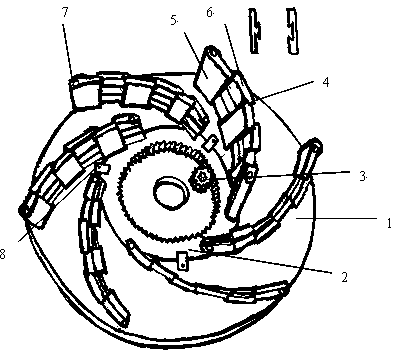
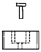
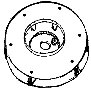
[0013] figure 1 It is one of the types of the structural principle diagram of the present invention. There is a circular groove in the middle of the impeller disc 1, and a ring 2 with teeth on the inner side is placed in the annular groove. The pinion gear 3 meshes, and there are 6 blades 4 on the top of the impeller disc 1, and the blades 4 are composed of several rectangular blocks 5 with convex grooves and rectangular blocks 6 with concave grooves connected in sequence. The cross-sectional view of the rectangular block 5 with the convex groove and the rectangular block 6 with the concave groove is shown in figure 1 Shown in the upper right of the above, the length of blade 4 can be elongated, shortened. There are two holes at both ends of each blade 4, and the screws 7 pass through the two holes on the blade to install the blades in the screw holes on the edge of ...


PUM


Abstract

A centrifugal pump impeller comprises an impeller disc and a plurality of blades. A round groove is formed in the middle of the impeller disc, a round ring with teeth on one inner side face is placed in an annular groove, one side with the teeth of the inner side face of the round ring is meshed with a small gear, screw holes identical in number are uniformly distributed on the round ring and at the edge of the impeller disc, two holes are arranged at two ends of each blade, and one end of each blade is fixed on the impeller disc while the other end of the same is fixed on the round ring with the teeth on the inner side face. Each blade can extend and contract but cannot disjoint. The round ring can be rotated by rotating the small gear, and then length of each blade can be changed, and mounting angle of each blade at an impeller inlet and an impeller outlet can be changed. The centrifugal pump impeller has the advantages that the blades of a centrifugal pump can be adjusted, so that performance of the centrifugal pump can be adjusted.

Description

technical field [0001] The invention relates to a centrifugal pump impeller, which belongs to thermal energy and power engineering equipment parts. Background technique [0002] [0003] The most commonly used pump is the centrifugal pump, followed by the axial flow pump, both of which work on different principles. Both have impellers with blades on them. The installation position of the blades on the impeller (such as inlet installation angle and outlet installation angle) has a great relationship with the lift and flow of the pump. The theoretical lift formula of a centrifugal pump is: . In the formula, β1 and β2 are the installation angles of the blades at the impeller inlet and outlet respectively, and this formula reflects the quantitative relationship between the blade position and the lift. In order to meet the needs of different heads, flow rates, rotational speeds, and powers, some axial flow pumps have produced blades that can be adjusted. However, centrif...

Claims


Application Information

Patent Timeline
Patent Type & Authority Applications(China)
IPC IPC(8): F04D29/22
Inventor 门立山
Owner DEZHOU UNIV
Why Eureka
Try Eureka