
Spouted bed reactor and olefin polymerization method thereof

A reactor and spouted bed technology, which is applied in the field of olefin polymerization, can solve the problems such as the deterioration of the axial flow of solid particles, the slowing of the downward flow speed, and the inability to eliminate the stagnation zone, so as to improve the particle movement and promote the flow. , the effect of improving heat transfer efficiency and mass transfer efficiency

Inactive Publication Date: 2014-11-05
ZHEJIANG UNIV
View PDF4 Cites 0 Cited by
  • Summary
  • Abstract
  • Description
  • Claims
  • Application Information

AI Technical Summary

Problems solved by technology

However, when the amount of gas diffused into the annular particle layer increases, the downward flow velocity of the solid particles in the annular layer slows down, making the axial flow mixing of the solid particles worse
This solution also does not eliminate the "stuck area"

Method used


Image

  • Spouted bed reactor and olefin polymerization method thereof
  • Spouted bed reactor and olefin polymerization method thereof
  • Spouted bed reactor and olefin polymerization method thereof

Examples


Embodiment 1

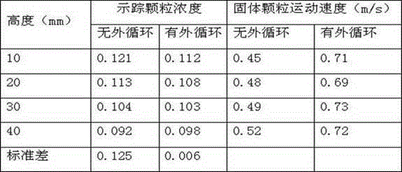
[0050] Example 1 and Comparative Example 1 are the results of laboratory cold model experiments. The main purpose is to compare the effect of external circulation of solid particles on the velocity of solid particles in the annulus area and the mixing of axial particles in the reactor by comparing with Comparative Example 1.

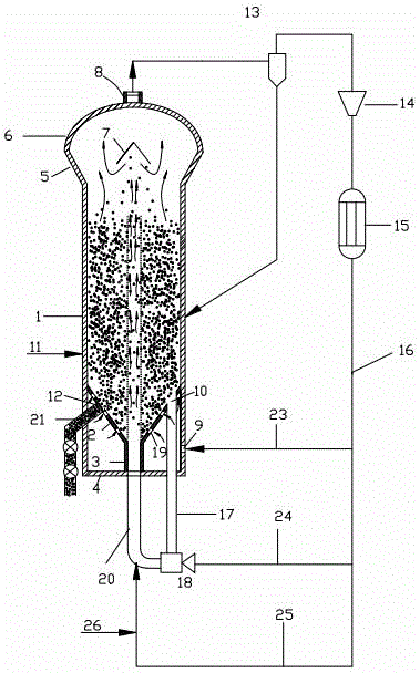
[0051] The structure of the spouted bed reactor cold model experimental device is as follows: figure 1 shown. and figure 1 The difference is that the cold mold experimental device does not have a gas external circulation system. The compressed air from the air compressor is measured by a glass rotameter and divided into three strands, one as the main airflow, the other as the auxiliary airflow, and the third as the auxiliary airflow. Gas-solid jet pump delivery gas. The diameter of the spouted bed reactor in the cold model experimental device is D = 150 mm, and the cylinder height H = 1000 mm. The size parameters of other parts of the spouted bed reac...

Embodiment 2

[0062] Example 2 and Comparative Example 2 are the results of industrial pilot thermal model experiments, the main purpose of which is to investigate the effect of external circulation of solid particles on particle agglomeration through comparison with Comparative Example 2.

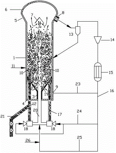
[0063] The structure of the industrial test device is as follows figure 2 shown. In the industrial experimental device, the diameter of the spouted bed reactor is D=420 mm, and the cylinder height H=2500 mm. The size parameters of other parts of the spouted bed reactor and the main parameters of the external circulation system of solid particles are shown in Table 3.

[0064] Table 3 The main parameters of the industrial experimental device

[0065] cylinder diameter D Conical Baffle Bottom Diameter 0.4D cylinder height H Conical Baffle Height 0.05H Expanded section diameter 1.8D Quantity of solid particle conveying system 2 Extended section height 0.2H Solid p...


PUM

PropertyMeasurementUnit
particle sizeaaaaaaaaaa

Abstract

The invention discloses a spouted bed reactor and an olefin polymerization method thereof. The spouted bed reactor comprises a spouted bed reactor main body, a circulation gas system, and a solid particle conveying device. With the solid particle conveying device, solid particles in the spouted fluidized bed is subjected to external circulation, such that the flowing of solid particles and gas in bed layer and especially annulus areas is promoted, particle mixing in the reactor is enhanced, retention area is eliminated, heat transfer efficiency and mass transfer efficiency are improved, and possibilities of wall adhesion agglomeration is reduced. A material outlet port is arranged on an external circulation pipe, and is connected to a material discharge system, such that material discharge efficiency can be improved. Auxiliary gas flow is delivered to a reaction bottom diameter-reduction section. Production performance can be adjusted by changing the composition of main gas flow and auxiliary gas flow.

Description

technical field [0001] The invention relates to the field of olefin polymerization, in particular to a spouted bed reactor and a method for olefin polymerization thereof. technical background [0002] The wall sticking and agglomeration of polymer is a problem often encountered in the production of olefin polymerization, but it has not been well solved so far. Taking the gas-phase polymerization reactor widely used in polyolefin production as an example, the wall-sticking and agglomeration of the polymer seriously affects the long-term stable operation of the gas-phase polymerization reactor. In severe cases, it may even block the pipeline and cause shutdown. Especially with the emergence of condensed state operation technology, by injecting condensate into the gas phase polymerization reactor, the heat removal capacity in the reactor is enhanced, so as to achieve the goal of greatly increasing the space-time yield of the reactor. Due to the existence of liquid, the viscou...

Claims


Application Information

Patent Timeline
Patent Type & Authority Patents(China)
IPC IPC(8): B01J8/24C08F10/00C08F2/34C08F2/01
Inventor 黄正梁顾玉彬周业丰王靖岱阳永荣廖祖维蒋斌波訾灿杨勇柳莺
Owner ZHEJIANG UNIV
Learn More