
Valve seat assembly of electronic expansion valve and manufacturing method of valve seat assembly

A technology of an electronic expansion valve and a manufacturing method, which is applied to refrigeration components, lift valves, valve devices, etc., can solve the problems of liquid refrigerant bubble bursting, easy interference, and noise generation, and achieve the effect of improving noise.

Inactive Publication Date: 2014-06-04
ZHEJIANG SANHUA INTELLIGENT CONTROLS CO LTD
View PDF6 Cites 25 Cited by
  • Summary
  • Abstract
  • Description
  • Claims
  • Application Information

AI Technical Summary

Problems solved by technology

However, the electronic expansion valve with this structure still has some room for improvement in terms of noise reduction.
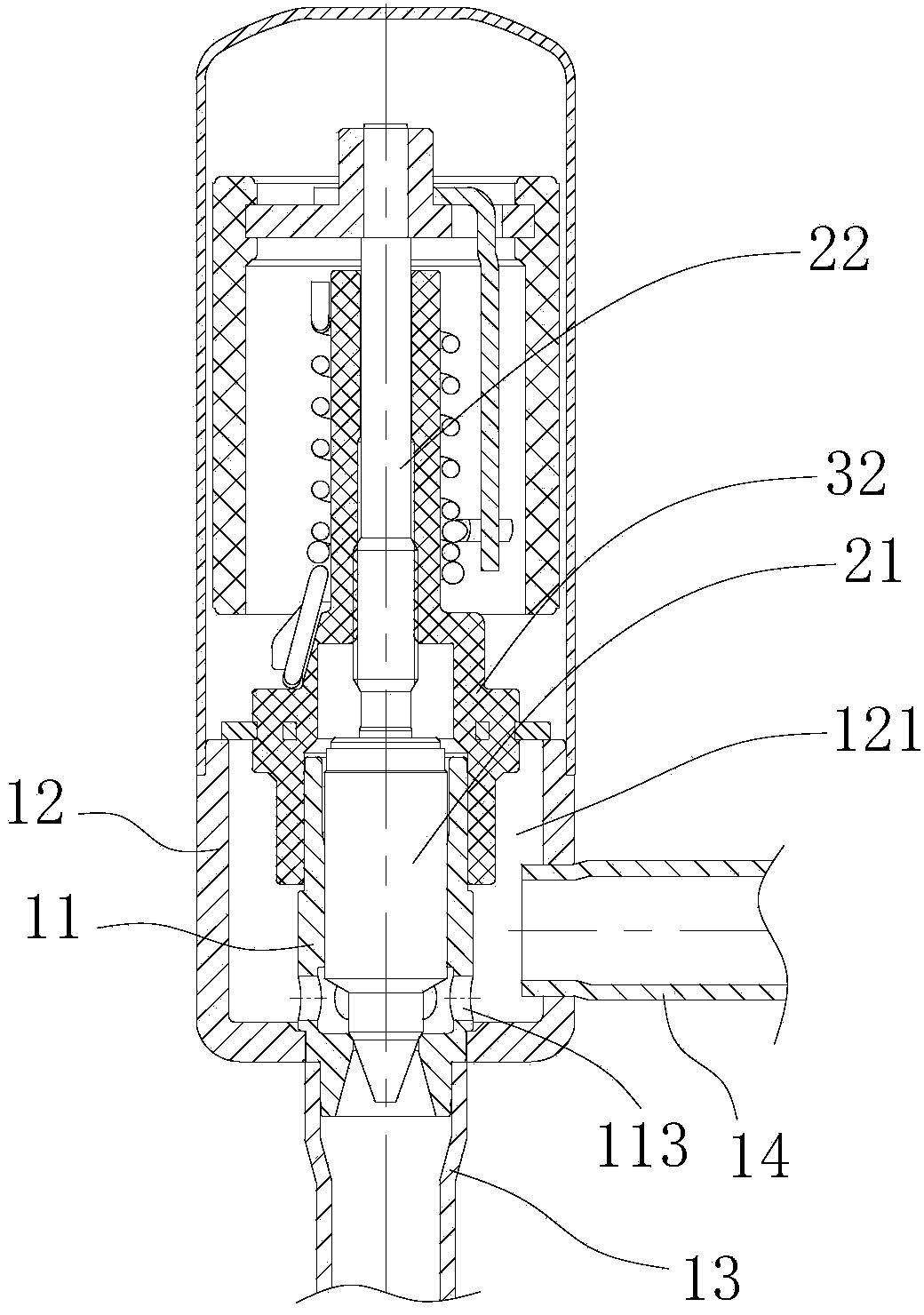
[0005] like figure 1 As shown, since the second connecting pipe 14 is inserted into the valve seat 12, the end of the connecting pipe extends into the valve cavity 121 formed by the valve seat 12, which destroys the integrity of the valve cavity 121 to a certain extent, making the original cylindrical shape The space (after assembling the valve core seat 11 and the valve needle 21, the space can be approximately regarded as a circular space) becomes irregular, and when the refrigerant enters the valve cavity 121, it is easy to cause interference during the flow process, thus Causes the bubbles in the liquid refrigerant to burst, resulting in noise
In addition, the end of the second connecting pipe protrudes into the valve cavity, and the length of the end protruding cannot be accurately controlled. In this way, the consistency of the assembly size of the connecting pipe cannot be guaranteed.

Method used


Image

  • Valve seat assembly of electronic expansion valve and manufacturing method of valve seat assembly
  • Valve seat assembly of electronic expansion valve and manufacturing method of valve seat assembly
  • Valve seat assembly of electronic expansion valve and manufacturing method of valve seat assembly

Examples


Embodiment Construction

[0040] In order to enable those skilled in the art to better understand the technical solutions of the present invention, the present invention will be further described in detail below in conjunction with the accompanying drawings and specific embodiments.

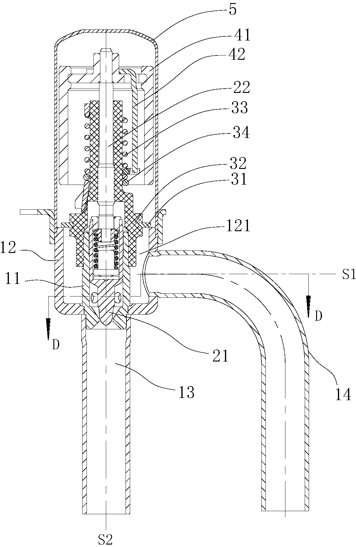
[0041] Please refer to figure 2 , figure 2 It is a structural schematic diagram of the electronic expansion valve provided by the present invention.

[0042] The electronic expansion valve provided by the present invention includes a valve seat assembly, a nut assembly, a valve needle screw assembly and a magnetic rotor assembly.

[0043] The nut assembly includes a nut 32 and a connecting piece 31 , the connecting piece 31 is integrally formed with the nut 32 as an insert, and the connecting piece 31 is welded and fixed to the valve seat 12 . The nut 32 is threadedly engaged with the screw mandrel 22 through the internal thread section provided in the middle. A guide section is provided on the inner edge of the lowe...


PUM


Abstract

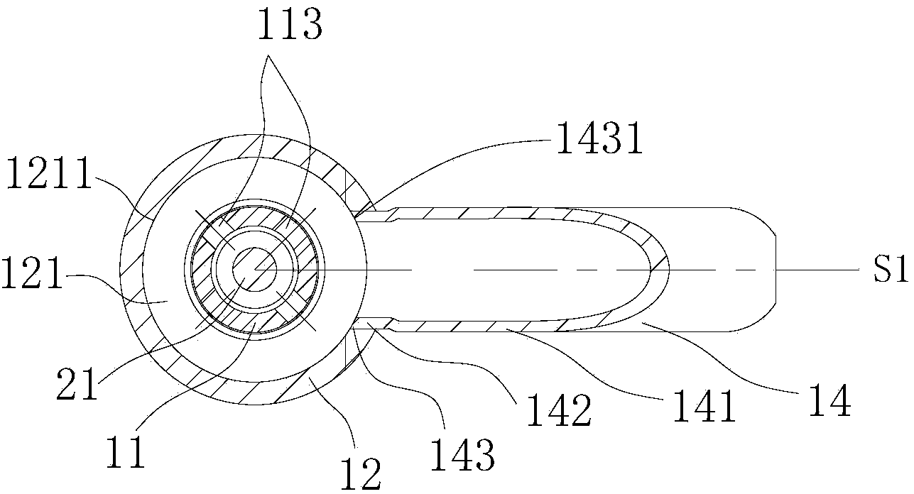
The invention discloses a valve seat assembly of an electronic expansion valve. The valve seat assembly of the electronic expansion valve is characterized by comprising a valve seat and a second connecting pipe, wherein the valve seat is provided with a valve cavity, the second connecting pipe is fixedly connected with the side wall of the valve seat, the first central axis of the second connecting pipe is perpendicular to the second central axis of the valve seat, and the edge face of the second connecting pipe does not exceed the inner circumferential face of the valve cavity in any section where the first central axis is located. The invention further provides a manufacturing method of the valve seat assembly of the electronic expansion valve. According to the valve seat assembly of the electronic expansion valve, it is ensured that the end of the second connecting pipe cannot extend into the valve cavity or damage the integrality of the valve cavity, the noise caused by irregular shape of the valve cavity when a refrigerant flows can be lowered, moreover, the matching length of the connecting pipe and the valve seat can be fully ensured, welding strength is improved, and the uniformity of the assembly size of the connecting pipe can be ensured.

Description

technical field [0001] The invention relates to the technical field of control valves, in particular to an electronic expansion valve for regulating fluid flow. Background technique [0002] In various refrigeration and heating equipment such as air conditioners, refrigerators, heat pump water heaters, etc., electronic expansion valves are usually used to regulate the flow of fluids. In addition, electronic expansion valves can also be used as pilot valves in solenoid valves. [0003] The electronic expansion valve usually includes a valve seat assembly, a nut assembly, a valve needle screw assembly, and a rotor assembly. The valve seat assembly usually includes a valve seat and a connecting pipe. The valve seat has a valve port, and the valve seat and the connecting pipe are usually welded together to form a valve. The seat assembly, the valve needle of the valve needle screw assembly is installed in the nut of the nut assembly. [0004] In order to solve the problem of t...

Claims


Application Information

Patent Timeline
IPC IPC(8): F16K1/42F25B41/06B23P15/00F25B41/34
CPCF16K1/42B23P15/001F25B41/31Y02B30/70
Inventor 不公告发明人
Owner ZHEJIANG SANHUA INTELLIGENT CONTROLS CO LTD
Learn More