
Test instrument mounting support

A test instrument and mounting bracket technology, which is applied in the field of test instrument mounting brackets, can solve problems such as hidden dangers of connection structures, easy shaking of test brackets, and reduced matching, and achieves the effect of improving accuracy and comprehensiveness.

Active Publication Date: 2014-06-04
SHANGHAI HUAHONG GRACE SEMICON MFG CORP
View PDF9 Cites 3 Cited by
  • Summary
  • Abstract
  • Description
  • Claims
  • Application Information

AI Technical Summary

Problems solved by technology

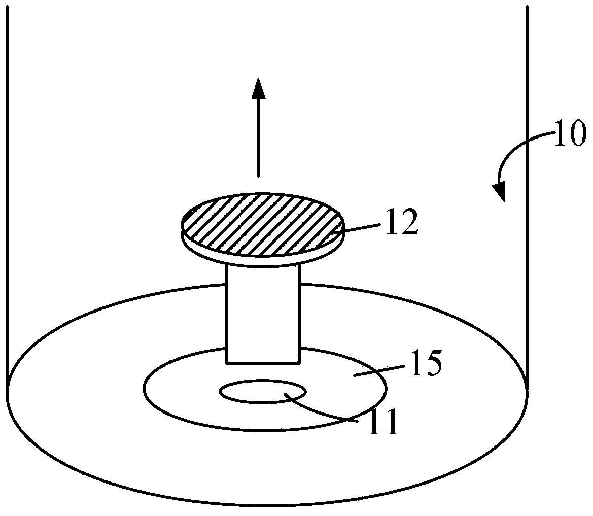
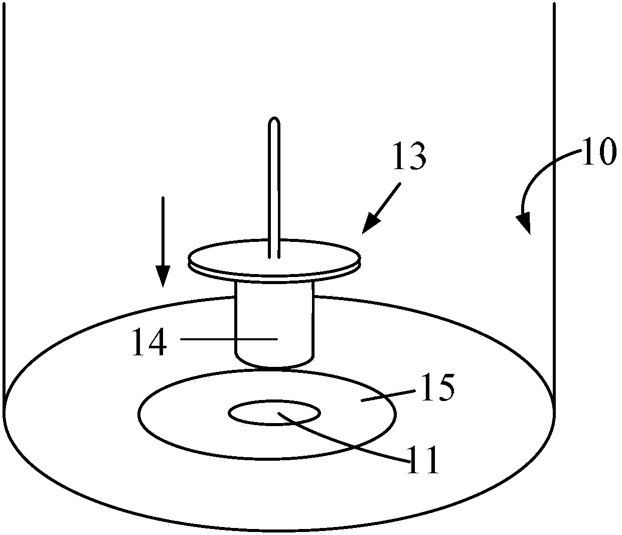
[0005] However, the existing test instrument installation bracket 13 only relies on the support of the fixed shaft 14. During the test, the test bracket is prone to shaking, thereby affecting the test results; moreover, the clean chamber 10 needs to maintain a certain degree of vacuum to ensure The steps of the subsequent semiconductor manufacturing process are carried out smoothly, but during the test process, the suction cup device 12 is repeatedly removed and reinstalled, which will cause the suction cup device 12 and the fixed plate to wear, thereby reducing the gap between the suction cup device 12 and the fixed plate in the clean chamber. matching, and the sealing effect between the suction cup device 12 and the installation hole 11, thereby reducing the sealing effect in the clean chamber 10
[0006] In addition, there are also structures such as lines and motors that need to be connected to the suction cup device 12 under the fixing plate of the clean chamber 10. Repeated disassembly and installation of the suction cup device 12 will cause hidden dangers in the connection structure between the suction cup device 12 and other components. , if the suction cup device 12 is installed incorrectly such as displacement, it will directly cause damage to the semiconductor device in the subsequent semiconductor manufacturing process

Method used


Image

  • Test instrument mounting support
  • Test instrument mounting support
  • Test instrument mounting support

Examples


Embodiment Construction

[0034] As mentioned in the background art, multiple process steps of semiconductor preparation need to be completed in a clean chamber to reduce pollution to semiconductor devices. In order to ensure the control accuracy of the process parameters in the preparation process steps and improve the quality of the final semiconductor device, before the preparation process, it is necessary to test the process parameters such as air pressure, temperature, and wind speed in the clean chamber to ensure that the environment in the chamber stability.

[0035] However, in the prior art, in order to ensure that the test instrument is located at the center of the clean chamber, during the installation of the test instrument mounting bracket for carrying the test instrument in the clean chamber, it is necessary to first remove the wafer suction cup located at the center of the clean chamber; After the test is completed, reinstall the wafer chuck. During the disassembly and reinstallation of...


PUM

PropertyMeasurementUnit
Heightaaaaaaaaaa

Abstract

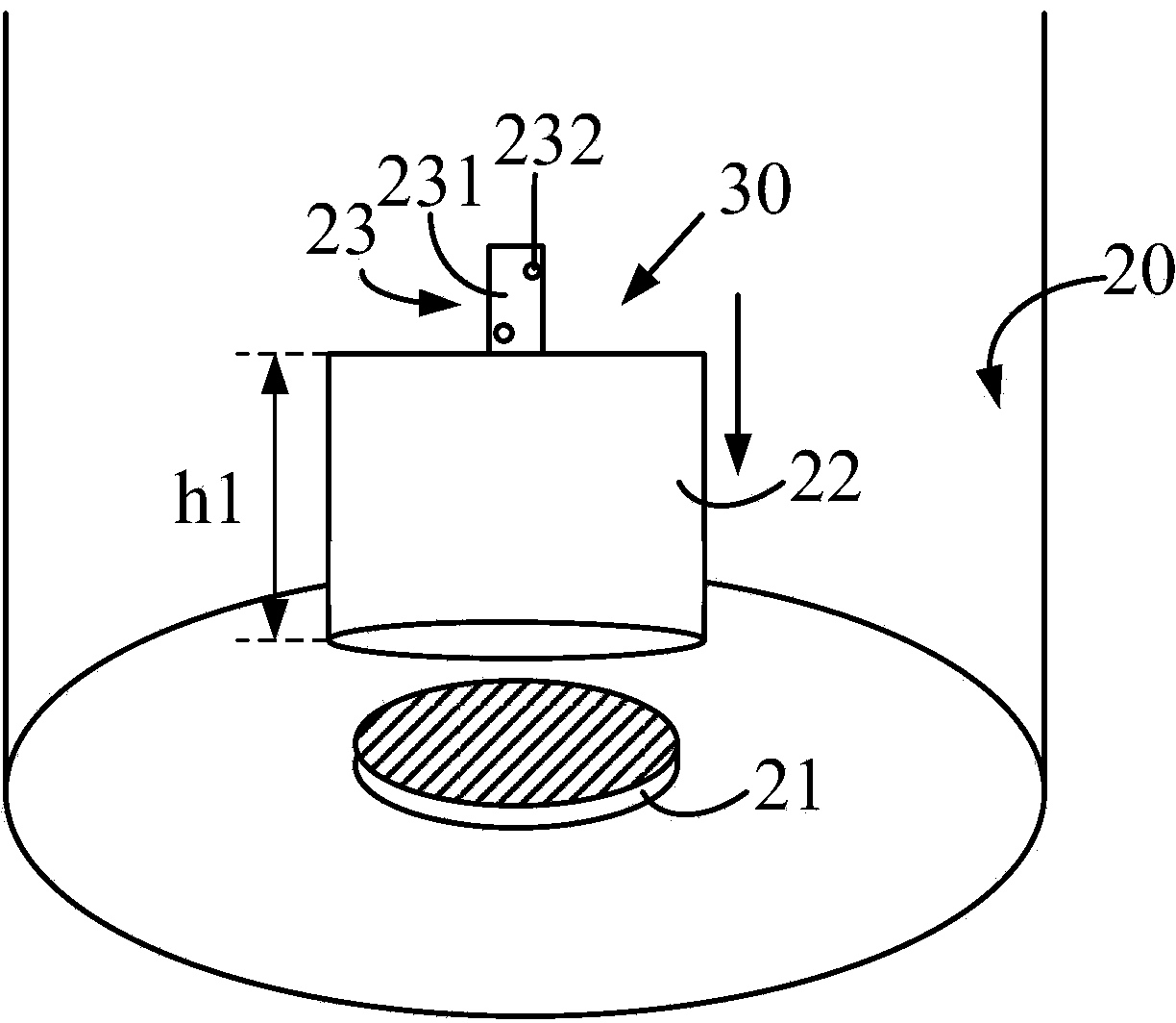
The invention provides a test instrument mounting support which is used for being placed in a clean cavity. The bottom of the clean cavity is provided with a wafer supporting device. The test instrument mounting support comprises an instrument mounting part and a supporting part. The supporting part is used for containing the wafer supporting device. The instrument mounting part is placed above the supporting part and is used for fixing a test instrument. During using, the instrument mounting part is used for mounting the test instrument, the supporting part of the test instrument mounting support is placed at the bottom of the clean cavity, and the wafer supporting device in the clean cavity is placed in the supporting part. Accordingly, under the condition that the wafer supporting device does not need to be moved, the test instrument is stably placed in the clean cavity, technology parameter testing in the clean cavity is carried out, and the problem that when the test instrument mounting support is mounted, the wafer supporting device is moved and mounted repeatedly, and accordingly parts in the clean cavity are damaged is effectively avoided.

Description

technical field [0001] The invention relates to the field of semiconductors, in particular to a test instrument mounting bracket. Background technique [0002] In an integrated circuit, tens of thousands to millions of components are integrated on a semiconductor substrate. The high precision requirements of integrated circuits make the various steps of integrated circuit preparation be completed in a dust-free clean room to avoid contamination of integrated circuits during the preparation process. In addition, during the fabrication of integrated circuits, parameters such as air pressure, temperature, and wind speed in the process need to be strictly controlled to ensure the quality of the obtained devices. [0003] For this reason, before the start of the integrated circuit manufacturing process, it is necessary to install testing instruments in the clean chamber to test the process parameters such as air pressure, temperature, and wind speed in the clean chamber to ensur...

Claims


Application Information

Patent Timeline
IPC IPC(8): G01D11/30H01L21/67
Inventor 马力鹏程蒙
Owner SHANGHAI HUAHONG GRACE SEMICON MFG CORP
Learn More