Inverse beamforming method and system

An inverse beam and array element technology, applied in the field of inverse beam forming methods and systems, can solve problems such as large computational load and complex algorithm, and achieve the effects of stable side lobes, simple and effective methods, and good display effects.

Inactive Publication Date: 2014-06-04
INST OF ACOUSTICS CHINESE ACAD OF SCI
View PDF4 Cites 9 Cited by
  • Summary
  • Abstract
  • Description
  • Claims
  • Application Information

AI Technical Summary

Problems solved by technology

[0004] The purpose of the present invention is to overcome the disadvantages of complex algorithm and large amount of calculation in the existing inverse beamforming method, so as to provide a simple and effective inverse beamforming method and system

Method used


Image

  • Inverse beamforming method and system
  • Inverse beamforming method and system
  • Inverse beamforming method and system

Examples


Embodiment Construction

[0042] The present invention will now be further described with reference to the drawings.

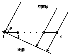
[0043] Before describing the method of the present invention in detail, first, a description will be given of the receiving dragline array to which the method of the present invention is applicable. figure 1 It is a schematic diagram of a receiving towed line array. The receiving towed line array is an equally spaced horizontal line array with the number of array elements. The target radiates signals from the θ direction and reaches the array element after propagating through the underwater acoustic channel. Taking the receiving dragline array as an example, the method of the present invention will be described in detail below.

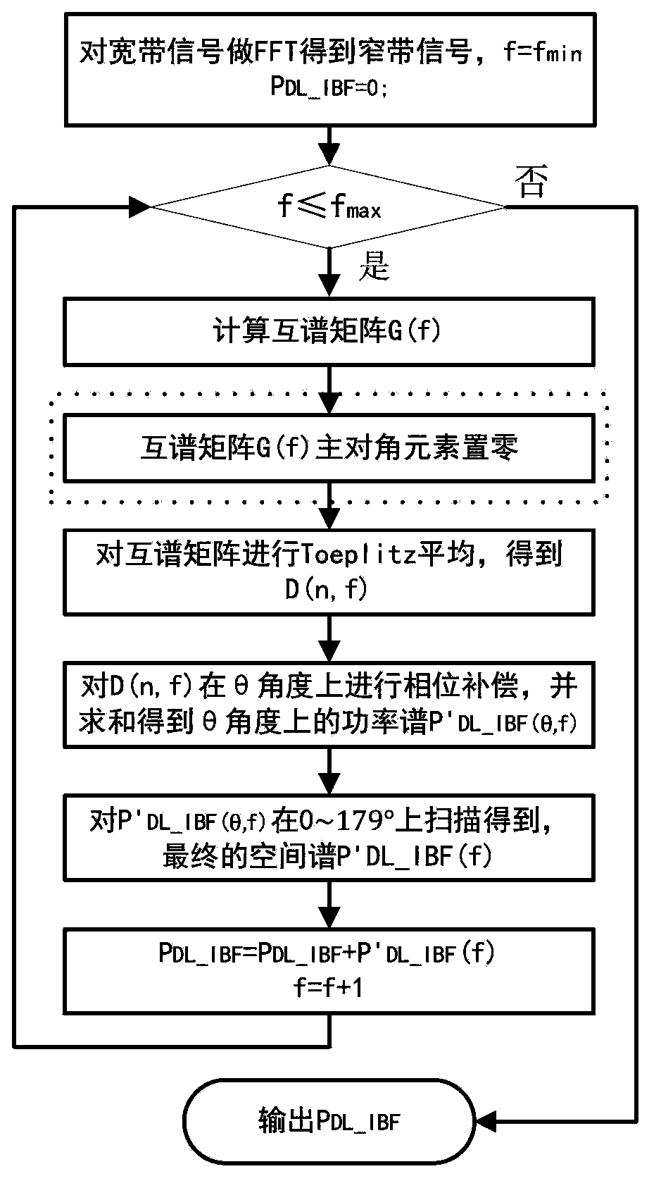
[0044] reference figure 2 , The method of the present invention includes the following steps:

[0045] Step 1). Receive the received signal of each element in the dragline array, perform discrete Fourier transform on the received signal, and set the initial value ...


PUM


Abstract

The invention relates to an inverse beamforming method. The method comprises the following steps: discrete fourier transform is performed on a received signal to obtain a frequency domain value of the signal; a cross-spectral matrix is calculated for receiving a towed line array according to the frequency domain value; correction is performed on main diagonal elements of the cross-spectral matrix; Toeplitz averaging is performed on the corrected cross-spectral matrix to convert the corrected cross-spectral matrix into one-dimensional distribution data having the spatial distribution characteristic; phase compensation is performed on the one-dimensional distribution data in the theta angle, and then the summing process is performed to obtain a power spectrum in the theta angle; spatial scanning is performed on the power spectrum in the range from 0 degree to 179 degrees to obtain a spatial spectrum P'(f) at the current signal frequency f; and P is made to be equal to the sum of P and P'(f), and f is made to be equal to f+1, and when f is less than or equal to fmax, the above steps are repeated, or else the operation is finished, so that the broadband inverse beamforming process is completed.

Description

Technical field [0001] The invention relates to the field of sonar signal processing, in particular to a method and system for inverse beam forming. Background technique [0002] With the continuous improvement of sonar technology, the energy of the target radiation signal is getting lower and lower, and the signal-to-noise ratio (SNR) of the signal received by each element in the receiving dragline array is getting lower and lower, resulting in direct inverse beam forming (INVERSEBEAMFORMIN, The display effect of the spatial spectrum data obtained by IBF) in the azimuth history diagram is poor, and even the target azimuth cannot be displayed well. [0003] Inverse beamforming requires directional vector data and cross-spectrum matrix data between array elements. Compared with other position elements, the main diagonal elements in the cross-spectrum matrix have larger noise energy and basically the same signal energy. Therefore, the difference in the main sidelobe energy of the sp...

Claims


Application Information

Patent Timeline
Patent Type & Authority Applications(China)
IPC IPC(8): G01S7/52
CPCG01S7/527G01S7/536
Inventor 郑恩明陈新华孙长瑜余华兵
Owner INST OF ACOUSTICS CHINESE ACAD OF SCI
Why Eureka
Try Eureka