Mixed type direct current breaker
A DC circuit breaker, a hybrid technology, applied in the direction of circuits, electrical components, electrical switches, etc., can solve the problems of unable to shut off the current, the breaking time is difficult to meet the DC transmission system, etc., to ensure safety, small loss, reduce effect of influence
- Summary
- Abstract
- Description
- Claims
- Application Information
AI Technical Summary
Problems solved by technology
Method used
Image
Examples
Embodiment 1
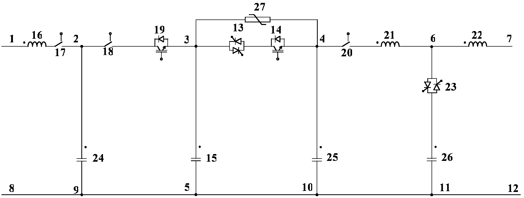
[0039] figure 1 Shown is Example 1 of the present invention. like figure 1 As shown, the present invention includes a first inductor 16, a first mechanical switch 17, a first capacitor 24, a second mechanical switch 18, a first electronic switch 19, a second capacitor 15, a second electronic switch 13, and a third electronic switch 14 , a voltage limiter 27 , a third capacitor 25 , a third mechanical switch 20 , a second inductor 21 , a fourth electronic switch 23 , a fourth capacitor 26 and a third inductor 22 . The second lead-out terminal of the first inductor 16 is connected to the first lead-out terminal of the first mechanical switch 17, the first lead-out terminal of the first capacitor 24, the second lead-out terminal of the first mechanical switch 17 and the first lead-out terminal of the second mechanical switch 18 One lead-out terminal is connected as the first connection point 2, the second lead-out terminal of the second mechanical switch 18 is connected with th...
Embodiment 2
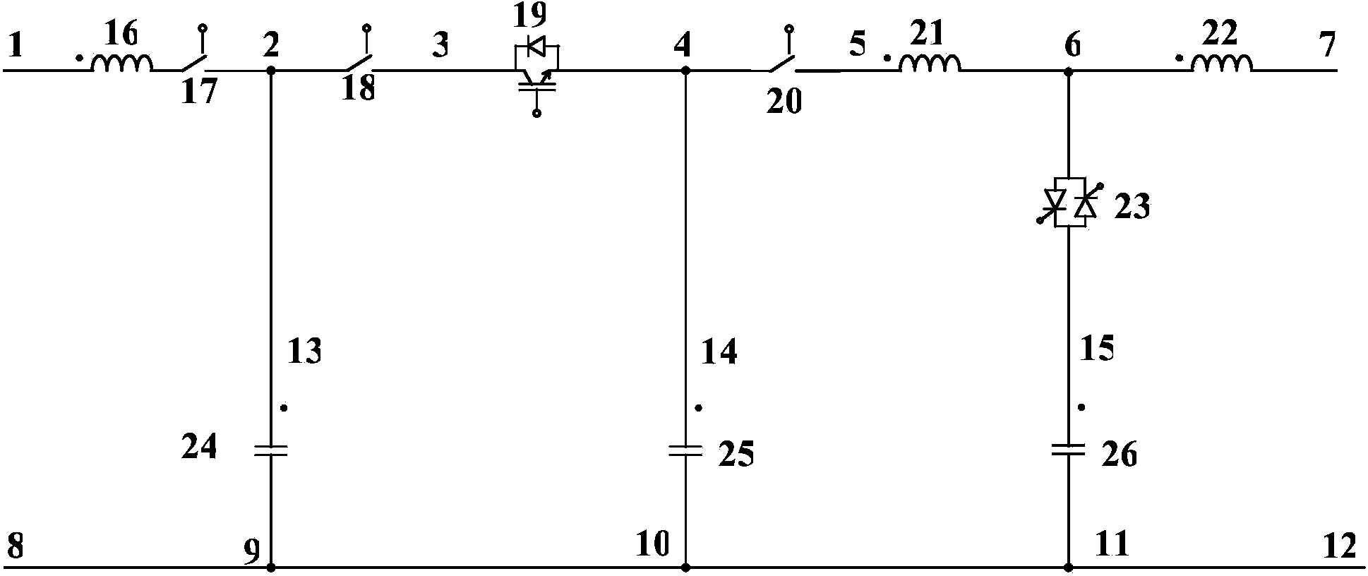
[0043] figure 2 Shown is Example 2 of the present invention. like figure 2 As shown, the present invention includes a first inductor 16, a first mechanical switch 17, a first capacitor 24, a second mechanical switch 18, a first electronic switch 19, a second capacitor 25, a third mechanical switch 20, a second inductor 21, The second electronic switch 23 , the third capacitor 26 and the third inductor 22 . The second lead-out terminal of the first inductor 16 is connected to the first lead-out terminal of the first mechanical switch 17, the first lead-out terminal of the first capacitor 24, the second lead-out terminal of the first mechanical switch 17 and the first lead-out terminal of the second mechanical switch 18 One lead-out terminal is connected as the first connection point 2, the second lead-out terminal of the second mechanical switch 18 is connected with the first lead-out terminal of the first electronic switch 19, the second lead-out terminal of the first elec...
Embodiment 3
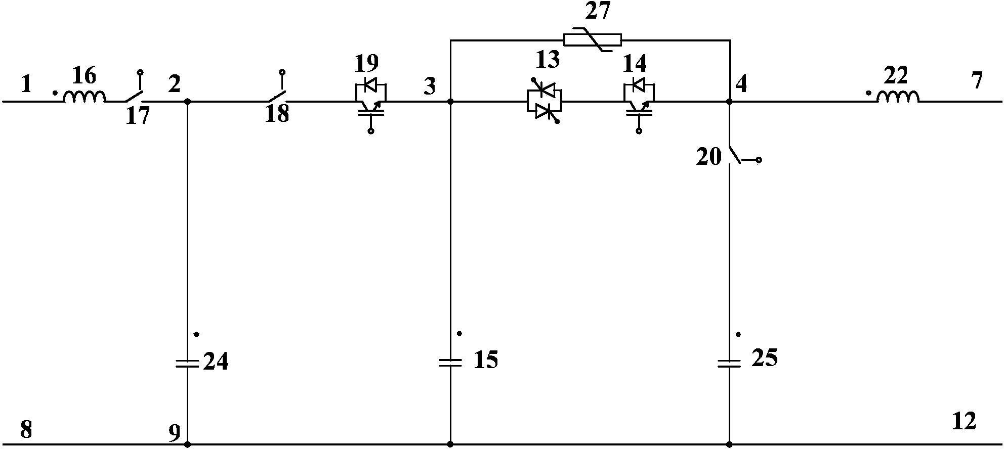
[0046] image 3 Shown is Example 3 of the present invention. like image 3 As shown, the present invention includes a first inductor 16, a first mechanical switch 17, a first capacitor 24, a second mechanical switch 18, a first electronic switch 19, a second capacitor 15, a second electronic switch 13, and a third electronic switch 14 , a voltage limiter 27 , a third capacitor 25 , a third mechanical switch 20 and a second inductor 22 . The second lead-out terminal of the first inductor 16 is connected to the first lead-out terminal of the first mechanical switch 17, the first lead-out terminal of the first capacitor 24, the second lead-out terminal of the first mechanical switch 17 and the first lead-out terminal of the second mechanical switch 18 One lead-out terminal is connected as the first connection point 2, the second lead-out terminal of the second mechanical switch 18 is connected with the first lead-out terminal of the first electronic switch 19, the second lead-o...
PUM
 Abstract
Description
Claims
Application Information
 - R&D
- Intellectual Property
- Life Sciences
- Materials
- Tech Scout
- Unparalleled Data Quality
- Higher Quality Content
- 60% Fewer Hallucinations
Browse by: Latest US Patents, China's latest patents, Technical Efficacy Thesaurus, Application Domain, Technology Topic, Popular Technical Reports.
© 2025 PatSnap. All rights reserved.Legal|Privacy policy|Modern Slavery Act Transparency Statement|Sitemap|About US| Contact US: help@patsnap.com


