
Horn antenna

A technology for antennas and horns, applied to waveguide horns, circuits, etc., can solve the problems of increasing the volume of the horn antenna 10, increasing production costs, etc.

Active Publication Date: 2014-06-04
WISTRON NEWEB
View PDF4 Cites 0 Cited by
  • Summary
  • Abstract
  • Description
  • Claims
  • Application Information

AI Technical Summary

Problems solved by technology

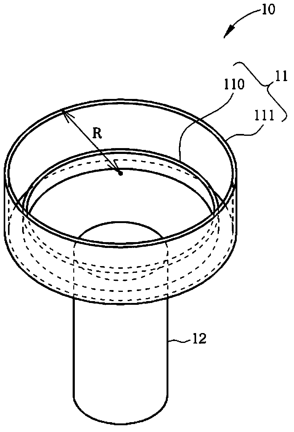
[0006] Traditionally, increasing the number of turns of the rings 110, 111 or increasing the opening radius R of the horn antenna 10 helps to improve the overflow loss, but this increases the volume of the horn antenna 10 and increases the production cost.

Method used


Image

  • Horn antenna
  • Horn antenna
  • Horn antenna

Examples


Embodiment Construction

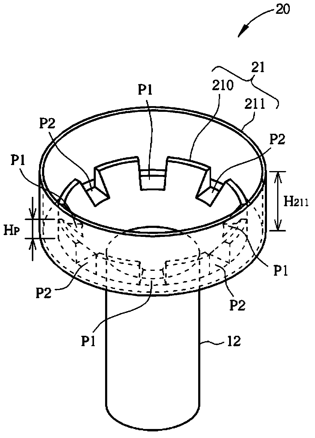
[0038] Please refer to figure 2 , figure 2 It is a schematic diagram of a horn antenna 20 according to Embodiment 1 of the present invention. The horn antenna 20 includes a cone 21 and a connector 12 . The cone 21 is used to receive the dish reflective surface (not drawn in figure 2 ) reflected satellite signal. The connector 12 is coupled to the cone 21 for coupling the horn antenna 20 to the waveguide (not shown in figure 2 ) to transmit the satellite signal to the waveguide. The inside of the cone 21 includes rings 210 , 211 , wherein the ring 210 is formed with a plurality of first notches P1 and a plurality of second notches P2 .

[0039] like figure 2 As shown, each second notch P2 is formed between two adjacent first notches P1 among the plurality of first notches P1, and vice versa, each first notch P1 is formed between two adjacent ones of the plurality of second notches P2 Between the second gap P2. Under this structure, the first notch P1 and the second...


PUM


Abstract

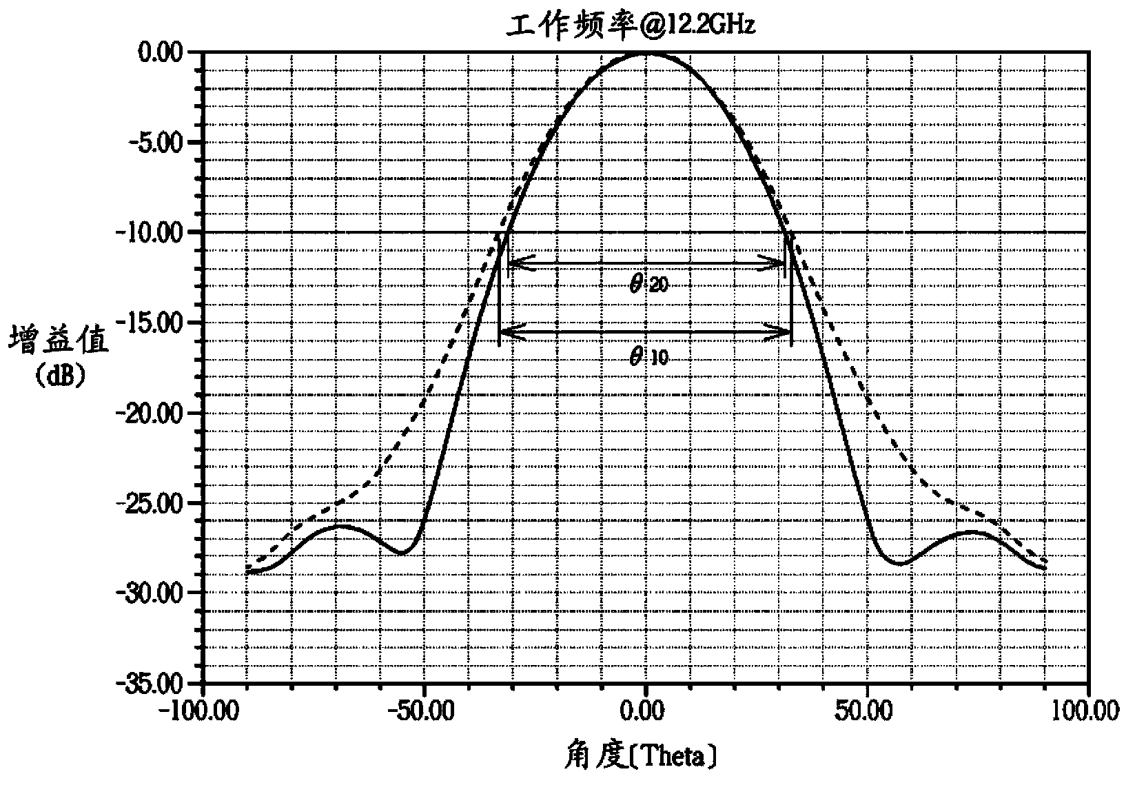
The invention discloses a horn antenna which is applied to a wave collector. The horn antenna comprises a cone and a connector. The cone is used for collecting a satellite signal. The cone comprises a number of ring bodies. A number of first notches and a number of second notches are formed on one ring body in a number of ring bodies. Each second notch is formed between two adjacent first notches in a number of first notches. The connector is coupled to the cone, and is used for coupling the horn antenna to a waveguide tube of the wave collector, so as to transmit the satellite signal to the waveguide tube. A number of first notches and a number of second notches are used as slots on the ring bodies to produce an interference effect, so that the beam field pattern of the horn antenna is adjusted.

Description

technical field [0001] The invention relates to a horn antenna, in particular to a horn antenna used for a wave collector, which utilizes the notch structure on the ring body to generate an interference effect to adjust the beam pattern of the horn antenna and reduce overflow loss. Background technique [0002] Generally speaking, the low noise block down-converter with Feedhorn (LNBF) of the satellite communication receiving device is set at the focal position of the dish reflector (Dish Reflector) to receive the radio wave signal reflected by the dish reflector , down-frequency the radio wave signal to an intermediate frequency, and then send it to a satellite signal processor at the back end for signal processing, so that the public can watch satellite TV programs. [0003] The wave collector consists of a feed horn, a waveguide and a low noise block down-converter (LNB). Among them, the horn antenna is used to collect and guide the signal reflected by the satellite ante...

Claims


Application Information

Patent Timeline
IPC IPC(8): H01Q13/02
Inventor 黄章修郭瞬仲詹兆凯
Owner WISTRON NEWEB
Learn More