
Pump and valve coordinated control method used for prestress intelligent tensioning device

A technology of intelligent tensioning and cooperative control, applied in mechanical equipment, fluid pressure actuation devices, fluid pressure actuation system testing, etc., can solve the problem of low load stiffness, low control precision, and complex structure of electro-hydraulic servo valves in pump control systems And other issues

Inactive Publication Date: 2019-04-30
TAIZHOU VOCATIONAL & TECHN COLLEGE
View PDF9 Cites 0 Cited by
  • Summary
  • Abstract
  • Description
  • Claims
  • Application Information

AI Technical Summary

Problems solved by technology

However, there are many defects in the valve control system: the structure of the electro-hydraulic servo valve is complex; it is particularly sensitive to the pollution of the working medium; Low, severe fever, etc.
But the disadvantage is that the moment of inertia of the motor and the oil pump is large, and the operation is not stable at low speed, so the response speed of the pump control system is slow and the control accuracy is low.
In addition, when the pump control system is working, the pressure in the back pressure chamber of the hydraulic actuator is small, resulting in low load stiffness of the pump control system

Method used


Image

  • Pump and valve coordinated control method used for prestress intelligent tensioning device
  • Pump and valve coordinated control method used for prestress intelligent tensioning device
  • Pump and valve coordinated control method used for prestress intelligent tensioning device

Examples


Embodiment Construction

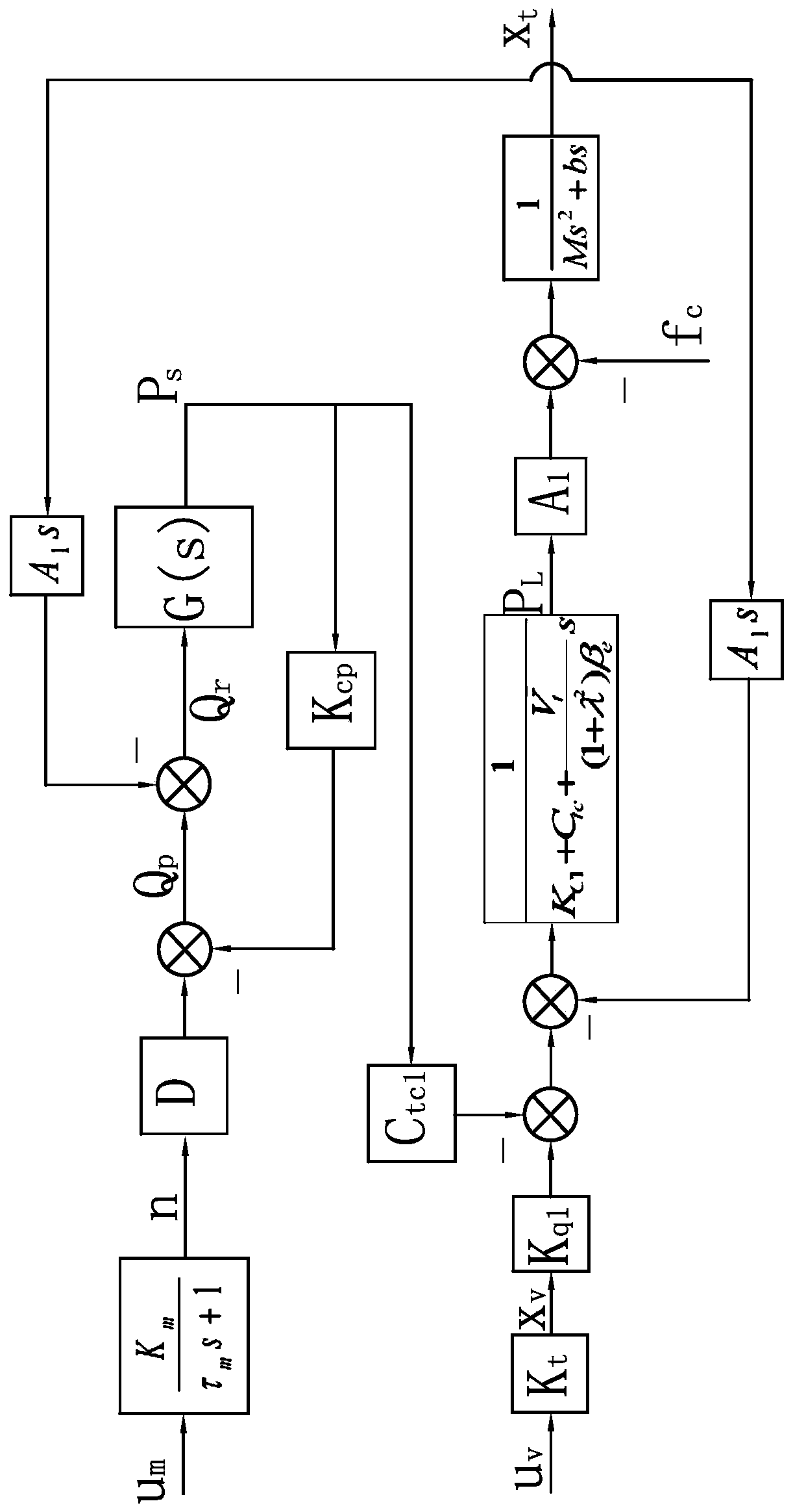
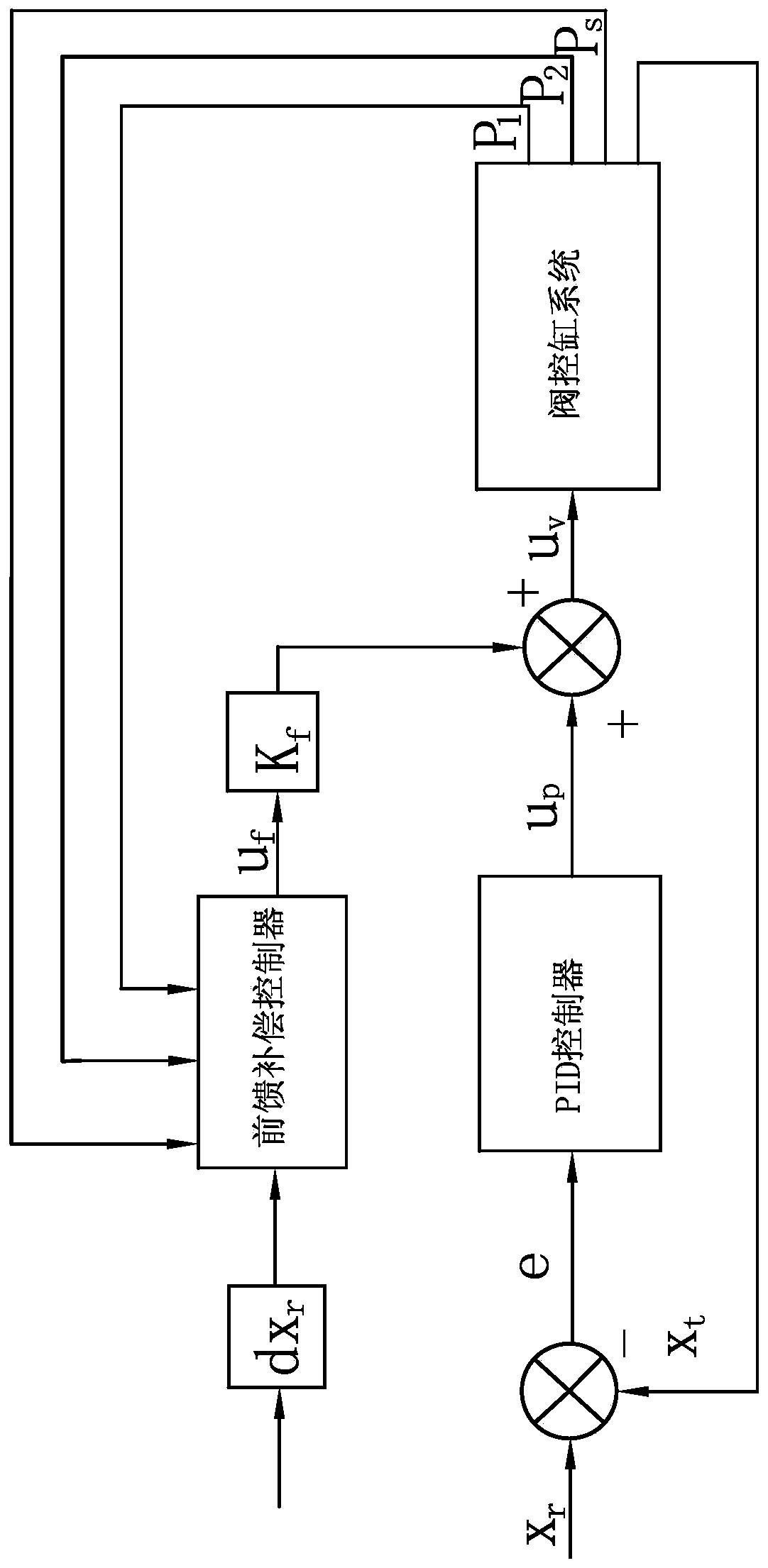
[0078] The following are specific embodiments of the present invention and in conjunction with the accompanying drawings, the technical solutions of the present invention are further described, but the present invention is not limited to these embodiments.

[0079] Such as Figure 1-3 As shown, the pump valve cooperative control method for prestressed intelligent tensioning equipment includes the following steps:

[0080] Build a model of the pump-valve coordinated control system;

[0081] The pump control part of the model of the pump-valve cooperative control system adopts the load flow prediction control algorithm, and obtains the predicted value of the displacement of the hydraulic cylinder by establishing the gray prediction model G(1,1) Then get the predicted value of the hydraulic cylinder speed by differentiation, and calculate the predicted value Q of the load flow L , according to the predicted value Q of the load flow L Obtain the predicted value Q of the output...


PUM


Abstract

The invention provides a pump and valve coordinated control method used for a prestress intelligent tensioning device, and belongs to the technical field of engineering construction such as bridge engineering, highways and tall buildings. According to the pump and valve coordinated control method used for the prestress intelligent tensioning device, the problem that control accuracy of an existingtechnology is not high is solved. The prestress intelligent tensioning device, and belongs to the technical field of engineering construction comprises the following steps that a mould of a pump andvalve coordinated control system is established; a loaded flow prediction control algorithm is adopted to a pump control part of the pump and valve coordinated control system, and pump control singleum output is obtained; a feed forward compensation PID control algorithm is adopted by a valve control part of the pump and valve coordinated control system, and valve control single uv output is obtained; the pump control single um and the valve control single uv are input into the pump and valve coordinated control system, and the rotating speed is controlled by a servo motor according to the pump control signal um, so that output flow of oil source is matched with the loaded flow, a stepping motor drives a direction switching valve to work according to the valve control signal uv, and thusadjustment of the loaded flow is realized. According to the pump and valve coordinated control method used for the prestress intelligent tensioning device, the dynamic response and control accuracy ofthe pump and valve coordinated control system can be improved.

Description

technical field [0001] The invention belongs to the technical field of engineering construction such as bridge engineering, expressways, and high-rise buildings, and relates to a pump-valve cooperative control method for prestressed intelligent tensioning equipment. Background technique [0002] The prestressed structure first achieved rapid development in bridge engineering, and now it has penetrated into various fields, such as high-rise buildings, lifting transportation, airstrips, TV towers, road interchange buildings, liquid storage tanks, marine structures, and prestressed concrete structures. It has been applied in ship hull structure, nuclear reactor vessel, special complex structure and so on. Prestressing technology has become an indispensable technology in large-span, large-space structures, high-rise structures, heavy-load structures, special structures, and new structural engineering. [0003] The prestressed intelligent tensioning equipment consists of two jac...

Claims


Application Information

Patent Timeline
IPC IPC(8): F15B19/00F15B9/09F15B13/16
CPCF15B9/09F15B13/16F15B19/007F15B2211/205F15B2211/405F15B2211/6656
Inventor 应一帜
Owner TAIZHOU VOCATIONAL & TECHN COLLEGE
Learn More