Metal belt type continuously variable transmission with symmetrical-moving conical discs

A continuously variable transmission, metal belt technology, applied in the direction of transmission, components with teeth, transmission control, etc., can solve the problems of less than expected fuel saving effect, no engine benefit, large loss of CVT efficiency, etc. , to achieve stable and reliable system operation, reduce energy consumption, improve transmission efficiency and parts life.

Inactive Publication Date: 2014-09-03
CHONGQING UNIV OF TECH +1
View PDF5 Cites 1 Cited by
  • Summary
  • Abstract
  • Description
  • Claims
  • Application Information

AI Technical Summary

Problems solved by technology

[0003] In principle, CVT can save fuel by making the engine always work on the economical curve, but due to the large efficiency loss of CVT itself, its fuel saving effect is not as ideal as expected
Currently, cars with CVTs have significantly improved fuel economy over cars with hydromechanical automatic transmissions (ATs), but are only comparable to cars with manual transmissions (MTs) and do not reflect the engine at its optimum Benefits of point work
[0004] Secondly, due to the existence of the axial deflection of the metal belt, the gear ratio of the continuously variable transmission and the increase of the working radius of the cone are limited.
In this way, on the one hand, the fuel-saving economic speed range of the vehicle is limited; on the other hand, the increase of the transmittable torque is limited; moreover, the axial deflection of the metal belt also makes the belt ring bear additional lateral bending stress, which affects the metal belt. life

Method used


Image

  • Metal belt type continuously variable transmission with symmetrical-moving conical discs
  • Metal belt type continuously variable transmission with symmetrical-moving conical discs

Examples


Embodiment Construction

[0020] The present invention will be described in further detail below in conjunction with the accompanying drawings and specific embodiments.

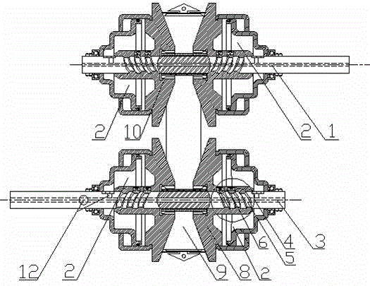
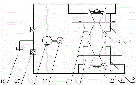
[0021] Such as figure 1 As shown, the cone-disc symmetrically moving metal belt type continuously variable transmission includes input shaft 1, output shaft 3, driving cone 10, driven cone 8, metal V-belt 9, cam pressurizing device 4 and pump-controlled closed hydraulic pressure transmission system. The driving cone 10 is installed on the input shaft 1 , and the driven cone 8 is installed on the output shaft 3 .

[0022] Among them, both the driving cone 10 and the driven cone 8 are composed of two movable cones, and the two movable cones on the same shaft are connected by a coupling structure or a connecting piece and are slidably matched with the corresponding shaft, and the metal V-belt 9 sleeves on the two movable cones on the input shaft 1 and the two movable cones on the output shaft 3. An oil cylinder 2 is respectively arran...


PUM


Abstract

The invention discloses a metal belt type continuously variable transmission with symmetrical-moving conical discs. The metal belt type continuously variable transmission comprises an input shaft, an output shaft, the drive and driven conical discs, a V metal belt, cam pressure device and a pump control closed type hydraulic transmission system. The drive and driven conical discs are respectively composed of two movable conical disc bodies, the V metal belt is sleeved with the two movable conical disc bodies on the input shaft and the two movable conical disc bodies on the output shaft, and the four movable conical disc bodies are respectively provided with an oil cylinder. The pump control hydraulic transmission system comprises a two-way hydraulic pump, a direct-current motor, one-way valves and an oil tank. One side of the two-way hydraulic pump is communicated with the two oil cylinders of the drive conical discs, and the other side of the two-way hydraulic pump is communicated with two oil cylinders of the driven conical discs. The cam pressure device is adopted for providing clamping force without consuming energy, a hydraulic control system is only used for changing the speed ratio and auxiliary clamping, the open type servo valve and proportional valve hydraulic control system is replaced with the pump control closed type hydraulic transmission system, in this way, overflow loss is reduced, energy consumption is greatly reduced, and the purposes that metal belt type continuously variable transmission saves more oil and is environmentally friendlier are achieved.

Description

technical field [0001] The invention relates to a belt type continuously variable transmission, especially for the control of a metal belt type continuously variable transmission (CVT). Background technique [0002] The metal belt continuously variable transmission (Continuously Variable Transmission, referred to as CVT) can realize the continuous change of the transmission ratio, so as to realize the best match between the transmission system and the engine working conditions, which can improve the fuel economy and power of the vehicle, and improve the handling Convenience and ride comfort, reducing emission pollution, is considered an ideal automotive transmission. CVT technology has become the main direction of the development of automobile variable speed transmission, its development potential is great, and it is one of the important development fields of automobile technology. However, the existing CVT technology still has the following shortcomings. [0003] In princi...

Claims


Application Information

Patent Timeline
Patent Type & Authority Applications(China)
IPC IPC(8): F16H7/20
CPCF16H9/125F16H61/0262F16H61/662F16H2061/66204
Inventor 郝建军
Owner CHONGQING UNIV OF TECH
Why Eureka
Try Eureka