Quartz clock and watch rotor wheel

A technology of rotor wheel and quartz clock, which is applied in the field of rotor wheel, can solve the problems of high power consumption, easy inclination, and high starting voltage, and achieve the effects of low power consumption, reduced rotation volume and low starting voltage

Active Publication Date: 2014-06-04
吴中一
View PDF6 Cites 6 Cited by
  • Summary
  • Abstract
  • Description
  • Claims
  • Application Information

AI Technical Summary

Problems solved by technology

[0006] 2) When assembling, first put the lower end shaft 13 of the rotor wheel 1 with the magnetic steel 3 installed through the center hole at the bottom of the magnetic pole groove 21 on the stator piece 2 and place it in the corresponding shaft hole, because the rotor wheel 1 disc 14 There must be a certain gap between the disk wall 15 and the inner side wall of the magnetic pole groove 21 (this is conducive to the rotation of the rotor wheel 1 under the action of the magnetic field force), so the rotor wheel 1 placed in the magnetic pole groove 21 Tends to tilt easily when not fitted with top cleats, therefore this creates some difficulty in fitting the top cleats
In order to overcome this defect, the commonly used method is: reduce the distance between the disk wall 15 and the inner wall of the magnetic pole groove 21 (including thickening the thickness of the disk wall 15 or reducing the diameter of the magnetic pole groove 21) so that the rotor wheel 1 is placed in the magnetic pole groove 21 with a small inclination angle, which is not conducive to the rotation of the rotor wheel 1
[0007] To sum up, in the prior art, the thickness of the disk wall 15 of the rotor wheel 1 and the disk 14 is not easy to be made too thin. According to the theory of rotation, this will make the starting voltage of the quartz clock and the quartz watch high when the stepping motor starts, and the power consumption is large. , for the following reasons:

Method used


Image

  • Quartz clock and watch rotor wheel
  • Quartz clock and watch rotor wheel
  • Quartz clock and watch rotor wheel

Examples


Embodiment Construction

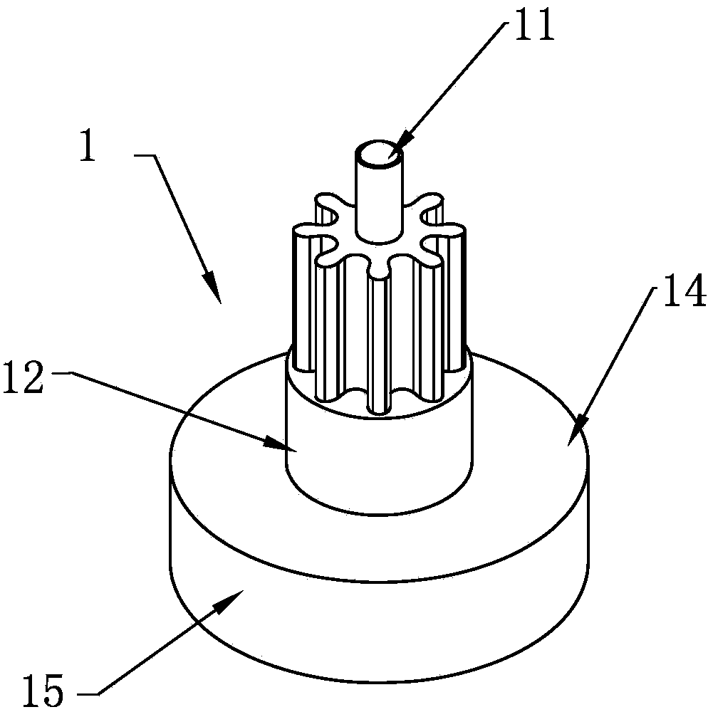
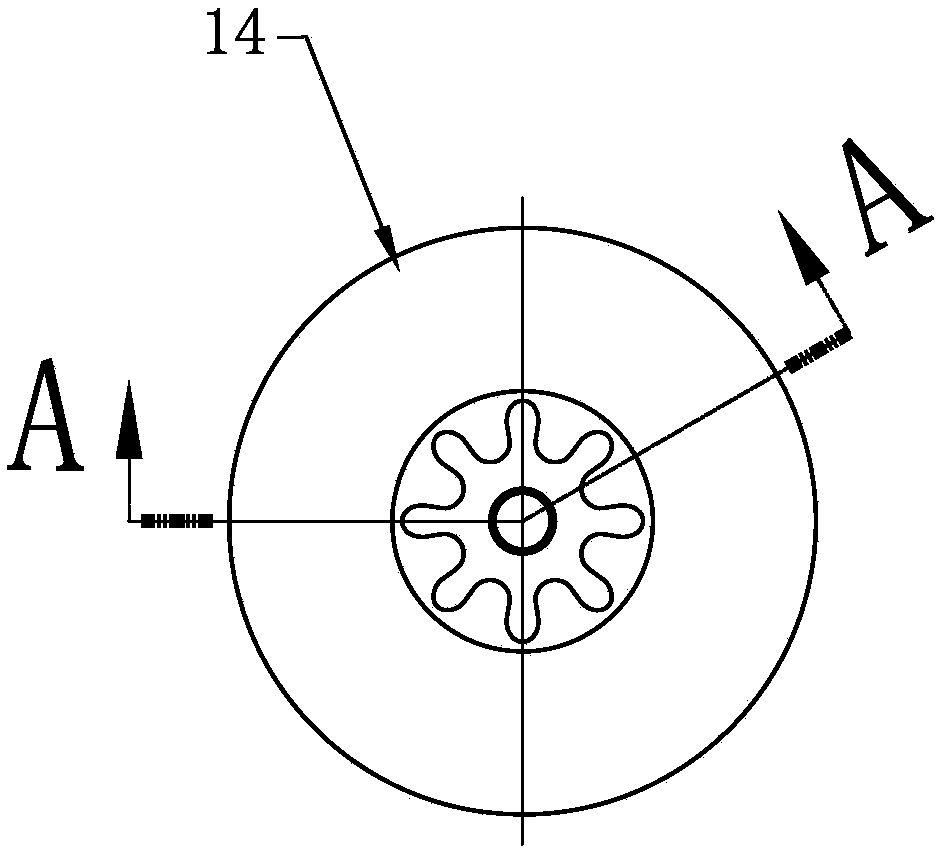
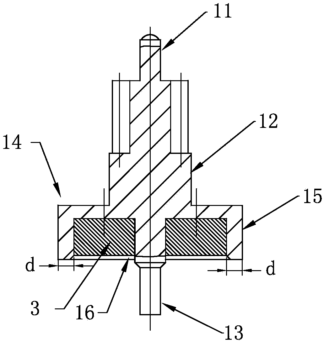
[0052] Such as Figure 4 , 5 Shown in and 6, quartz clock of the present invention, table rotor wheel 1 are also provided with upper end shaft 11, central axis 12, wheel disc 14, wheel disc 14 inner groove 16 and lower end shaft 135 the same as rotor wheel 1 of the prior art Part, except that the other four parts of the disc 14 are the same as the rotor wheel 1 of the prior art, only its disc 14 is different in shape from the circular disc 14 of the rotor wheel 1 in the prior art, and the inner groove of the disc 14 16 The cross-sectional shape is also circular as in the prior art, and the magnetic steel 3 is fixedly installed in the inner groove 16 . The profile cross-sectional shape of wheel disc 14 can be regular quadrilateral to regular octagon, and the inner groove 16 of described wheel disc 14 is the circular groove concentric with regular quadrilateral to regular octagon inscribed circle, as Figure 7 , 8As shown in and 9, the cross-sectional shape of a regular quadr...


PUM


Abstract

The invention discloses a quartz clock and watch rotor wheel which is low in starting voltage and power consumption. The rotor wheel comprises a wheel disc, wherein the edge of the cross section of the wheel disc is provided with at least three symmetric edge lugs which are the same in thickness, the outmost edges of all the edge lugs are located on the same excircle with the axis of the wheel disc as a center, and the wall thickness of the largest transverse portion of each edge lug is 0.01 mm-0.3 mm larger than that of other portions of the disc wall of the wheel disc. According to the rotor wheel, on the condition that injection molding is safely formed, the thickness of the disc wall of the wheel disc is effectively reduced, and accordingly the weight is correspondingly reduced, namely rotation inertia of the rotor wheel can be effectively reduced; due to the action of the edge lugs, during assembling, the inclination angle of the rotor wheel is smaller than the inclination angle of a rotor wheel which is assembled in the prior art. On the condition that identical materials and magnetic steel are used, the rotation inertia of the rotor wheel is effectively reduced, and accordingly the starting voltage and the power consumption are low; additionally, the rotation inertia is small, and accordingly the rotor wheel is reliable when moving.

Description

technical field [0001] The invention relates to a rotor wheel used for quartz clocks and quartz watches, in particular to a rotor wheel capable of reducing the amount of rotation. Background technique [0002] Rotor wheel 1 is an important part in quartz clocks and quartz watches, such as figure 1 , 2 As shown in and 3, it consists of five parts: the upper shaft 11, the central shaft 12, the wheel disc 14, the inner groove 16 of the wheel disc 14 and the lower end shaft 13 formed by one injection molding, as Figure 10 As shown, the rotor wheel 1 is installed in the magnetic pole groove 21 of the stator piece 2, its upper end shaft 11 is placed in the corresponding shaft hole of the upper splint, and its lower end shaft 13 passes through the center hole at the bottom of the magnetic pole groove 21 and placed on the main splint In the corresponding shaft hole, the magnetic steel 3 is fixedly installed in the inner groove 16 of the wheel disc 14 , and the shaft teeth are she...

Claims


Application Information

Patent Timeline
Patent Type & Authority Applications(China)
IPC IPC(8): H02K1/27H02K37/10G04C3/14
Inventor 吴中一
Owner 吴中一
Why Eureka
Try Eureka