
Brushless direct current motor and commutation method thereof

A technology of brushed DC motors and commutators, which is applied in the direction of electronic commutators, electromechanical devices, electrical components, etc., and can solve problems such as large torque fluctuations, affecting the stability of motor operation, and limiting the application of brushless DC motors

Inactive Publication Date: 2014-06-04
SHENYANG POLYTECHNIC UNIV
View PDF4 Cites 0 Cited by
  • Summary
  • Abstract
  • Description
  • Claims
  • Application Information

AI Technical Summary

Problems solved by technology

[0003] A brushless DC motor is usually composed of three parts: a position detection device, an electronic commutator and a motor body. Since the motor winding is commutated in units of the number of slots per pole and phase, the torque ripple is very large, which affects the smooth operation of the motor. characteristics, which largely limits the application of brushless DC motors

Method used


Image

  • Brushless direct current motor and commutation method thereof
  • Brushless direct current motor and commutation method thereof
  • Brushless direct current motor and commutation method thereof

Examples


Embodiment Construction

[0019] The present invention will be described in more detail below in conjunction with the embodiments shown in the accompanying drawings.

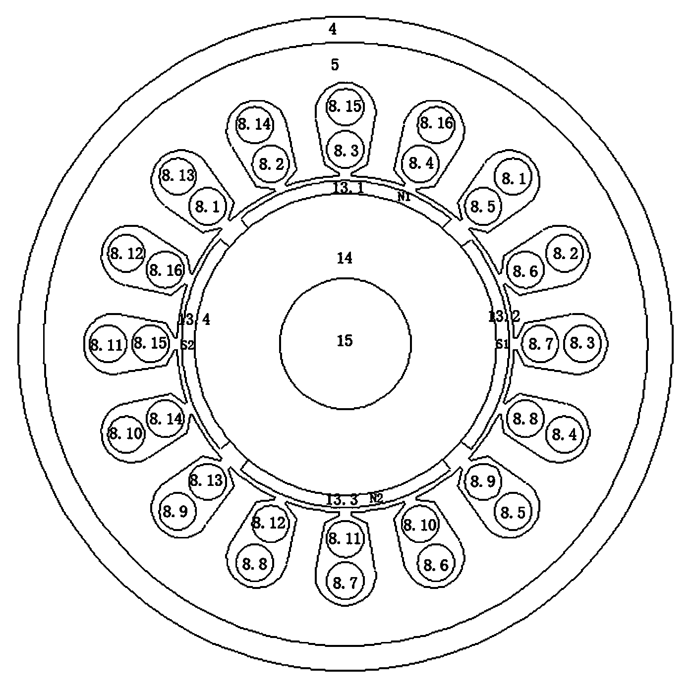
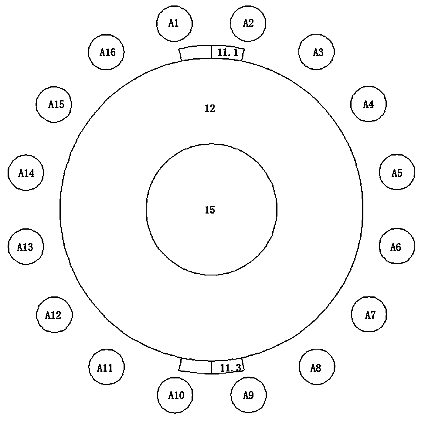
[0020] An embodiment of the present invention is a 4-pole 16-slot internal rotor brushless DC motor, such as figure 1 As shown, it includes end cover 1, bearing 2, fastener 3, casing 4, armature core 5, cooling fan 6, windshield 7, armature winding 8, electronic commutator 9, commutation element bracket 10 , Position indicating permanent magnet 11, position indicating permanent magnet support 12, rotor permanent magnet main pole 13, rotor core 14 and rotating shaft 15.

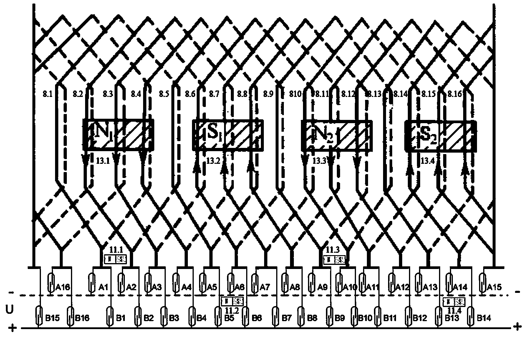
[0021] In the embodiment, the permanent magnet main pole 13 of the rotor is a four-pole surface-mounted structure, and the main permanent magnet pole 13 of the rotor is composed of N1, S1, N2 and S2 arranged alternately in polarity, respectively numbered 13.1, 13.2, 13.3, 13.4, Such as figure 2 shown. The rotor core 14 is made of thin silicon steel sheets or a whole ...


PUM


Abstract

The invention provides a brushless direct current motor and a commutation method thereof. The commutation method is characterized in that the commutation method is performed on grooves one by one. An electronic commutator is composed of a reed switch commutation element array A and a commutation element array B which act as both detection elements and commutation elements. The electronic commutator with integration of detection and commutation is triggered to be on and off by a position-indicating permanent magnet so that commutation of an armature coil is realized. A brushless direct current motor comprises an end cap, a bearing, a fastener, a machine shell, an armature iron core, a cooling fan, a protective fan cover, an armature winding, the electronic commutator, a commutation element bracket, the position-indicating permanent magnet, a position-indicating permanent magnet bracket, a rotor permanent magnet main magnetic pole, a rotor iron core and a rotating shaft 15. The commutation method can be performed like a common machine by which a brush direct current motor is commutated, speed is regulated by regulating direct current supply voltage, and a rotating direction of the motor is changed by changing polarity of the direct current supply voltage so that torque pulsation is substantially reduced, and stability in operation of the brushless direct current motor is enhanced.

Description

technical field [0001] The invention relates to an electromechanical energy conversion device, in particular to a non-contact commutation brushless DC motor and a commutation method thereof, belonging to the technical field of brushless DC motor design and manufacture. Background technique [0002] Ordinary DC motors have many advantages such as simple structure and easy speed adjustment. In particular, since the commutation elements are basically commutated slot by slot, the torque ripple is small and the motor runs smoothly. [0003] A brushless DC motor is usually composed of three parts: a position detection device, an electronic commutator and a motor body. Since the motor winding is commutated in units of the number of slots per pole and phase, the torque ripple is very large, which affects the smooth operation of the motor. However, the application of brushless DC motors is limited to a large extent. Therefore, the development, development and production of brushless...

Claims


Application Information

Patent Timeline
Patent Type & Authority Applications(China)
IPC IPC(8): H02P6/16H02K29/03
Inventor 安跃军安辉孙丹闵家龙薛丽萍
Owner SHENYANG POLYTECHNIC UNIV
Learn More