Mowing device for lawn mower and mounting method for mowing device

A technology of cutting device and installation method, which is applied in the direction of cutters, harvesters, agricultural machinery and implements, etc., which can solve the problems of high energy consumption, uneven length of cut grass, and high manufacturing cost, so as to reduce energy consumption and wind resistance , the effect of quick assembly

Active Publication Date: 2014-06-11
POSITEC POWER TOOLS (SUZHOU) CO LTD
View PDF5 Cites 4 Cited by
  • Summary
  • Abstract
  • Description
  • Claims
  • Application Information

AI Technical Summary

Problems solved by technology

However, the manufacturing process of this cutting blade with flanging is complicated, and the manufacturing cost is quite high.
[0003] During the working process of the lawn mower, due to the high speed of the cutting blade, the cutting blade with turning blades will encounter greater wind resistance, so the energy consumption will be relatively high. In terms of battery packs, the working time of a single battery pack will be shortened, which is detrimental to the work efficiency and performance evaluation of the lawn mower
Simultaneously, the cutting blade always cuts in the same cutting plane, and the probability of the broken grass being cut again and the cutting length are random, so the length of the broken grass produced is uneven. Poor function of shredding grass and technical problems of high energy consumption

Method used


Image

  • Mowing device for lawn mower and mounting method for mowing device
  • Mowing device for lawn mower and mounting method for mowing device
  • Mowing device for lawn mower and mounting method for mowing device

Examples


Embodiment Construction

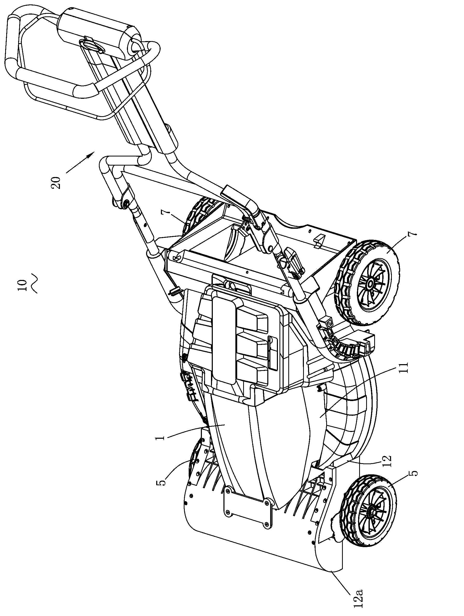
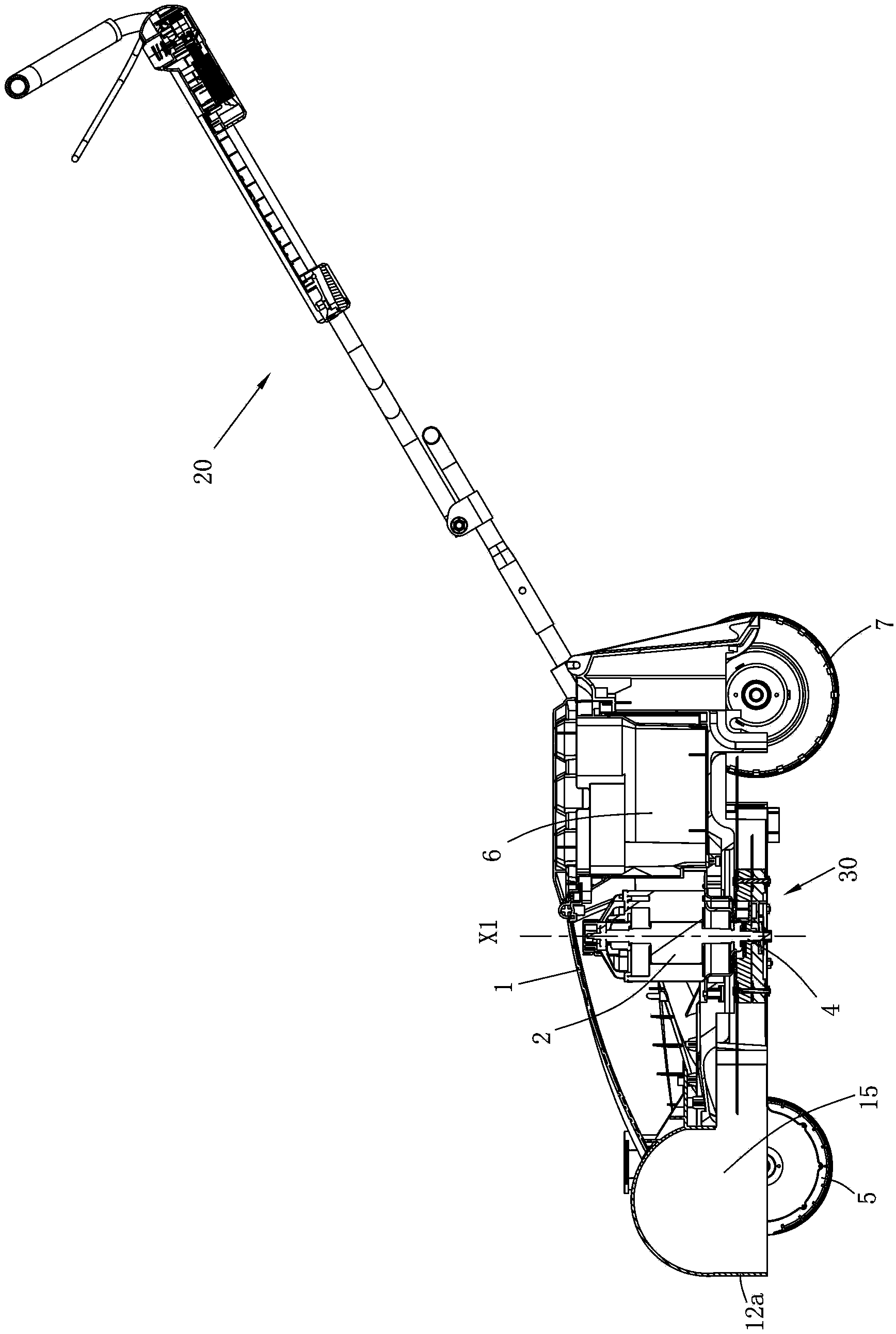
[0047] refer to figure 1 , figure 2 As shown, the power lawn mower 10 of the first embodiment of the present invention has a casing 1, and a plurality of rollers are arranged at the bottom of the casing 1 for supporting the lawnmower to move on the ground. The rollers include a pair of front wheels 5 supporting the front casing and a pair of rear wheels 7 supporting the rear casing. An operating mechanism 20 extending to the rear of the lawn mower 10 is connected to the rear casing for controlling the operation of the lawn mower 10 . The casing 1 includes a top wall 11 and a surrounding wall 12 extending from the top 11 to the ground. The top 11 and the surrounding wall 12 form a cutting cavity 15 . When the mower 10 advances in the cutting direction, grass enters the cutting cavity 15 from the bottom of the front end portion 12a of the surrounding wall. The casing 1 is provided with a driving device. The driving device in this embodiment is a motor 2. The output shaft 4 i...


PUM


Abstract

The invention discloses a mowing device for a lawn mower and a mounting method for the mowing device. The mowing device comprises a rotary disc, a plurality of mowing blades which are arranged along the circumference of the rotary disc and disposed at different phases and fastening units for connecting the plurality of mowing blades with the rotary disc. A plurality of accommodation grooves extending from the outer edge of the rotary disc to the center of the rotary disc radially are formed in the rotary disc and are distributed in at least two different mowing planes along the axial direction of the rotary disc, and the accommodation grooves are provided with openings in the periphery of the rotary disc to enable the mowing blades to be inserted in the accommodation grooves. The mowing device is low in cost, high in mowing effect, capable of reducing energy consumption of the lawn mower and rapid and convenient to mount.

Description

technical field [0001] The invention relates to a cutting device of a lawnmower and a method for installing the cutting device. Background technique [0002] Ordinary power lawn mowers usually use a single-piece cutting blade. The middle part of the cutting blade is a connecting part, which is connected to the output shaft of the power lawn mower through a fastening device, and the output shaft is driven to rotate for cutting the lawn. In order to improve the cutting effect, the structure of the single-piece cutting blade has been improved. The most common way is to set widened flanges at both ends of the cutting blade, and set the main mounting hole in the middle to connect to the lawn mower through a fastening device. The output shaft is driven by the output shaft to form an airflow in the cutting cavity of the lawn mower, throwing the cut grass in the cavity, so that there is an opportunity to cut the broken grass again, so that the final cut grass Relatively fine. Howe...

Claims


Application Information

Patent Timeline
Patent Type & Authority Applications(China)
IPC IPC(8): A01D34/73A01D34/68
Inventor 张士松庞晓丽钟红风吴晓雨徐静涛
Owner POSITEC POWER TOOLS (SUZHOU) CO LTD
Why Eureka
Try Eureka