Circular combined type plant root collecting device

A technology of root exudates and collection device, which is applied in the fields of botanical equipment and methods, gardening, gardening tools/equipment, etc., can solve the problem of not being able to collect a large amount of root exudates at one time, unable to circulate the culture solution, and the root exudate is not pure enough. and other problems, to achieve the effect of satisfying a large number of development applications, high purity and simple manufacturing process

Inactive Publication Date: 2014-06-11
JIANGSU UNIV
View PDF8 Cites 4 Cited by
  • Summary
  • Abstract
  • Description
  • Claims
  • Application Information

AI Technical Summary

Problems solved by technology

[0003] The purpose of the present invention is to solve the problems that the culture solution cannot be circulated and the operation is not simple enough, a large amount of root exudates cannot be collected at one time and the collected root exudates are not pure enough

Method used


Image

  • Circular combined type plant root collecting device
  • Circular combined type plant root collecting device
  • Circular combined type plant root collecting device

Examples


Embodiment 1

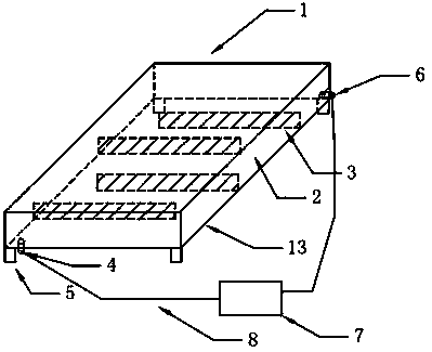
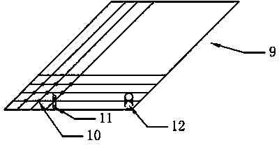
[0017] Embodiment 1: a combined circulation type root exudate collection device, comprising a collection tank, a beam support 3, a planting plate 9, a planting hole 10, a hose 8 and a kneading pump 7. It is characterized in that the collection tank (such as figure 1 , Figure 4 As shown) consists of two transverse blocking plates 1, two longitudinal plates 2, and a bottom plate 13, the two transverse blocking plates 1 are located parallel at both ends, the two longitudinal plates 2 are parallel at both sides, and the bottom plate 13 is located at the bottom of the collection tank to form a collection The rectangular frame of the groove, the base plate 13 one corner is provided with the liquid outlet pipe 4, is provided with the liquid inlet pipe 6 on the longitudinal plate on the diagonal line of the liquid outlet pipe, is provided with the support foot 5 on the four corners below the base plate 13, and the beam support member 3 Arranged equally with the cross-blocking plate 1...

Embodiment 2

[0018] Embodiment 2 is further limited to Embodiment 1. The material of the transverse blocking plate 1, the longitudinal plate 2, the beam support member 3, the bottom plate 13, and the feet 5 are all glass, and the thickness of the glass is 0.5 cm.

Embodiment 3

[0019] Embodiment 3 is further limited to Embodiment 1 or 2. The planting plate 9 is an opaque plastic plate, and the planting hole 10 has a diameter of 1 cm.


PUM


Abstract

The invention discloses a circular combined type plant root collecting device, comprising a collecting groove, crossbeam support pieces, a planting plate, planting holes, a hose and a kneading pump, wherein the collecting groove is composed of cross block plates, longitudinal plates and a base plate, wherein the cross block plates are in parallel and positioned at two ends, the longitudinal plates are in parallel and positioned at two sides, the base plate is positioned at the bottom of the collecting groove, and thus forming a rectangular frame of the collecting rove; one corner of the base plate is provided with a liquid outlet pipe; the longitudinal plate in the diagonal line of the liquid outlet pipe is provided with a liquid inlet pipe; the four corners of the lower surface of the base plate are provided with stand bars; the crossbeam support piece is arranged in parallel with the cross block plates, and the length of the e crossbeam support piece is smaller than these of the cross block plates; two adjacent crossbeam support pieces are respectively connected with the longitudinal plates at two sides in a staggering manner; the bottoms of the crossbeam support pieces are connected with the base plate; the planting plate is placed on the crossbeam support pieces, the length of the planting plate is accordant with the internal size of the collecting groove; the planting plate is provided with a plurality of planting hole along the transverse and longitudinal directions; one corner of the planting plate is provided with a liquid adding pipe; planting pipes are arranged in the planting holes; the kneading pump, the liquid outlet pipe and the liquid inlet pipe are connected by the hose.

Description

technical field [0001] The invention relates to a collection device, which is aimed at a collection device for root exudates under hydroponic conditions. Background technique [0002] Existing root exudate collection devices, such as the "combined root exudate collection device" invented by Northeast Agricultural University, have some shortcomings and deficiencies. On the one hand, they cannot circulate the culture solution to ensure that the culture solution has sufficient oxygen; It's not simple enough. Some other root exudate collection devices, such as the "root exudate collection device" invented by South China Agricultural University, the "crop root exudate collection method" invented by the graduate students of Northeast Geography and Agricultural Ecology of the Chinese Academy of Sciences, and the "root exudate collection method" invented by Shanghai University. Excretion collection devices have some shortcomings and deficiencies. On the one hand, they cannot collec...

Claims


Application Information

Patent Timeline
Patent Type & Authority Applications(China)
IPC IPC(8): A01G7/00A01G31/02
CPCY02P60/21
Inventor 吴易孙见凡司春灿祈珊珊黄萍薛永来杜道林
Owner JIANGSU UNIV
Why Eureka
Try Eureka