
Carbon fiber composite material and method for preparing the same

A composite material, carbon fiber technology, applied in thin material processing, chemical instruments and methods, synthetic resin layered products, etc., can solve problems such as limited adjustment or change effect

Active Publication Date: 2014-06-11
IND TECH RES INST
View PDF4 Cites 13 Cited by
  • Summary
  • Abstract
  • Description
  • Claims
  • Application Information

AI Technical Summary

Problems solved by technology

[0004] Usually, the preparation of multi-layer polymer fiber composite materials is mainly through lamination, that is, stacking multiple polymer fiber layers, and adjusting the fiber angle between the upper and lower polymer fiber layers to achieve the required mechanical or physical properties, or Adjust the thickness of the laminate or the thickness of the polymer, however, the effect of such adjustments or changes is still limited

Method used


Image

  • Carbon fiber composite material and method for preparing the same
  • Carbon fiber composite material and method for preparing the same
  • Carbon fiber composite material and method for preparing the same

Examples


Embodiment 1

[0025] see Figure 1A to Figure 1C , illustrating the method for preparing the carbon fiber composite material of the present invention.

[0026] Such as Figure 1A As shown, a first carbon fiber layer 10 is prepared, having an opposite first surface 10a (such as the aforementioned first side) and a second surface 10b (second side), formed on the first surface 10a of the first carbon fiber layer 10 There is a resin 12 containing carbon nanotubes, and the surface of the carbon nanotubes has reactive functional groups to bond with the resin 12 . In this schematic diagram, the prepreg-molded carbon fiber layer is used as the first carbon fiber layer 10, so that both the first surface 10a and the second surface 10b of the first carbon fiber layer 10 have the resin 12, in other words, the resin 12 is wrapped Cover the first carbon fiber layer 10.

[0027] However, the resin may also be formed on a single surface of the first fiber layer.

[0028] In a specific embodiment, at lea...

Embodiment 2

[0035] continue Figure 1B steps such as Figure 2A As shown, in this embodiment, before shaping the laminate 1, a third carbon fiber layer 16 is combined on the second side of the first carbon fiber layer 10, so that the first carbon fiber layer 10 is sandwiched between the Between the second carbon fiber layer 14 and the third carbon fiber layer 16 .

[0036] Afterwards, plastic processing is carried out to obtain such as Figure 2B The carbon fiber composite shown in 2.

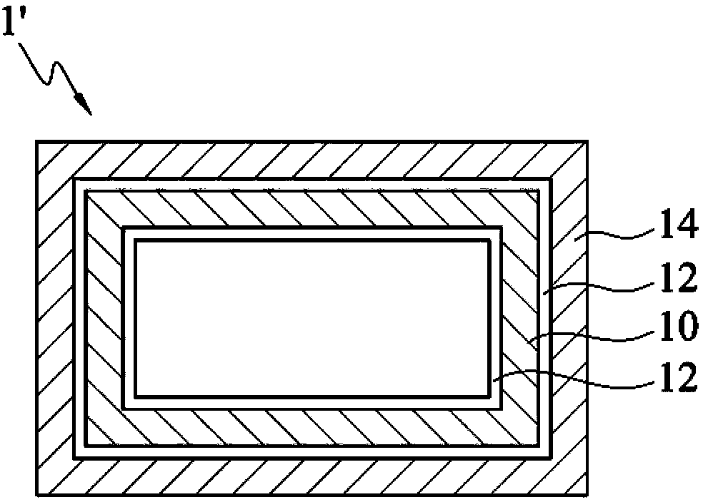
[0037] According to the method of the present invention, the present invention also provides a carbon fiber composite material 1', 2, comprising: a first carbon fiber layer 10; a second carbon fiber layer 14; and sandwiched between the first carbon fiber layer 10 and the second carbon fiber layer The resin 12 between 14, wherein the resin 12 contains carbon nanotubes, and the surface of the carbon nanotubes has reactive functional groups for bonding with the resin.

[0038] The carbon fiber composite m...


PUM

PropertyMeasurementUnit
Thicknessaaaaaaaaaa

Abstract

A carbon fiber composite material and a method for preparing the same are provided. The method includes binding a first surface of a first carbon fiber layer with a second carbon fiber layer to obtain a laminated article, wherein a resin containing carbon nanotubes is formed on the first surface or a second surface of the first carbon fiber layer and the carbon nanotubes have functional groups on the surfaces thereof; and shaping the laminated article.

Description

technical field [0001] The present invention relates to a carbon fiber composite material and its preparation method, in particular to a carbon fiber composite material with high vibration damping and its preparation method. Background technique [0002] With the progress of the times, the increase of user needs and the demand for energy saving, etc., have made polymer fiber composite materials develop towards lightweight and high strength. Sports equipment such as bicycles, golf clubs, rackets, bats, etc., wind power blades and industrial production equipment are all accompanied by the development of light weight and increased strength. At the same time, it is necessary to solve the problems caused by the structural vibration of polymer fiber composite materials. Vibration suppression to improve user comfort and performance of industrial production equipment applications. [0003] For example, the mechanical arm for transportation will produce displacement, deformation and...

Claims


Application Information

Patent Timeline
IPC IPC(8): B32B37/00B32B9/04B32B27/04B32B27/38
CPCB32B5/26B32B9/047B32B7/12B32B27/08B32B27/12B32B27/20B32B27/306B32B27/34B32B27/38B32B2250/42B32B2255/02B32B2255/26B32B2260/021B32B2260/046B32B2262/106B32B2262/108Y10T428/239Y10T428/25Y10T156/1044B32B37/12B32B37/14
Inventor 刘时州叶日翔施志哲
Owner IND TECH RES INST
Learn More