Turnover device

A flipping device and flipping part technology, applied in packaging and other directions, can solve the problems of uneven patch, increased consumption, skewed attaching part, etc., and achieve the effect of good attaching quality, simple structure and high attaching efficiency

Inactive Publication Date: 2014-06-11
YIHE PRECISION IND SUZHOU
View PDF8 Cites 5 Cited by
  • Summary
  • Abstract
  • Description
  • Claims
  • Application Information

AI Technical Summary

Problems solved by technology

[0002] In the electronics industry or consumables industry, for the sake of beauty or protection, the product needs to be attached to the key parts. The existing process is mostly manual attachment. When attaching the long strip, due to the long attachment length, The patch is relatively thin, and multiple people are required to work together when attaching the patch, which may easily cause defects such as skewed attachment, uneven patch, deformation, or bubbles left after attachment, which not only affects the appearance of the product, but also increases consumption. Increase follow-up operations for trimming, so a device that can be quickly attached is urgently needed

Method used


Image

  • Turnover device
  • Turnover device
  • Turnover device

Examples


Embodiment 1

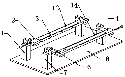
[0024] Such as figure 1 As shown, the turning device includes a frame 8 and a first turning part 1 and a second turning part 7 which are sequentially arranged on the frame 8, each turning part has a superimposed surface, and the first turning part 1 and the second turning part The overlapping surfaces of the parts 7 can be turned over and attached to each other.

[0025] The first reversing part 1 comprises a first placement platform 2 and an adsorption device, the adsorption device comprises an adsorption hole 3 and a negative pressure device arranged on the first placement platform 2, and the negative pressure device comprises an adsorption chamber fixedly connected with the first placement platform 2 (not shown in the figure) and an air pump (not shown in the figure), and the adsorption chamber and the air pump are connected by an air guide tube (not shown in the figure). The first placement platform 2 is also provided with a positioning block (not shown in the figure).

...

Embodiment 2

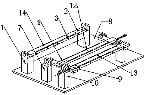
[0030] Such as figure 2 As shown, the turning device includes a frame 8 and a first turning part 1, a second turning part 7 and a third turning part 10 which are sequentially arranged on the frame 8, each turning part has a superimposed surface, and the first turning part The superimposed surfaces of the part 1 and the second reversed part 7 can be reversed and bonded to each other, and the superimposed surfaces of the second reversed part 7 and the third reversed part 10 can be reversed and bonded to each other.

[0031] The first reversing part 1 comprises a first placement platform 2 and an adsorption device, the adsorption device comprises an adsorption hole 3 and a negative pressure device arranged on the first placement platform 2, and the negative pressure device comprises an adsorption chamber fixedly connected with the first placement platform 2 and the air pump, the adsorption chamber and the air pump are connected by an air guide tube. The first placement platform...

Embodiment 3

[0039]The rest are the same as in Embodiment 2, the difference is that the first turning part 1 includes a first adsorption device, and the first adsorption device includes an adsorption hole and a negative pressure device arranged on the first placement table 2, and the negative pressure device includes the same as the first suction device. A placement table 2 is fixedly connected to the adsorption chamber and the air pump, and the adsorption chamber and the air pump are connected by an air duct.

[0040] The second placement table 4 is also provided with a second fast positioning and a pneumatic clamping mechanism.

[0041] The working principle of the turning mechanism is as follows:

[0042] The first placement platform 2 is provided with a first positioning block, the patch 12 is placed on the first placement platform 2, the adsorption device is turned on, and the patch 12 is adsorbed on the first placement platform 2 due to negative pressure. The second placement table ...


PUM


Abstract

A turnover device is used for performing surface mounting on products. The turnover device comprises a frame and at least two turnover portions; the turnover portions are arranged on the frame in turn; every turnover portion comprises at least one composite surface; the composite surfaces of the adjacent turnover portions are attached to each other in a turnover mode. According to the turnover device which is used for performing the surface mounting on the products, one layer or multi-layer attachment can be rapidly achieved through turnover match of the turnover portions and accordingly the attachment quality is improved and the working efficiency is increased.

Description

technical field [0001] The invention relates to an overturning device, in particular to an overturning device for pasting patches of products. Background technique [0002] In the electronics industry or consumables industry, for the sake of beauty or protection, the product needs to be attached to the key parts. The existing process is mostly manual attachment. When attaching the long strip, due to the long attachment length, The patch is relatively thin, and multiple people are required to work together when attaching the patch, which may easily cause defects such as skewed attachment, uneven patch, deformation, or bubbles left after attachment, which not only affects the appearance of the product, but also increases consumption. Follow-up operations are added for trimming, so a device that can be quickly attached is urgently needed. Contents of the invention [0003] In order to solve the above technical problems, the object of the present invention is to provide a tur...

Claims


Application Information

Patent Timeline
Patent Type & Authority Applications(China)
IPC IPC(8): B65B33/02
Inventor 王少波
Owner YIHE PRECISION IND SUZHOU
Why Eureka
Try Eureka