Multistage middle shaft rapid flushing gate

A fast flushing and rotating shaft technology, which is applied in water conservancy projects, artificial waterways, sea area projects, etc., can solve problems such as uncontrollable drainage of irrigation canals, and achieve the effects of uniform force, fast opening, and reduced size and strength requirements

Active Publication Date: 2014-06-11
WUHAN SHENGYU DRAINING SYST
View PDF6 Cites 16 Cited by
  • Summary
  • Abstract
  • Description
  • Claims
  • Application Information

AI Technical Summary

Problems solved by technology

[0004] Such a weir plate setting results in that the drainage of the pipe canal can only be controlled at the maximum flow rate, and the drainage of the irrigation canal cannot be controlled according to the external conditions.

Method used


Image

  • Multistage middle shaft rapid flushing gate
  • Multistage middle shaft rapid flushing gate
  • Multistage middle shaft rapid flushing gate

Examples


Embodiment Construction

[0025] The present invention will be further described in detail below in conjunction with the accompanying drawings and specific embodiments.

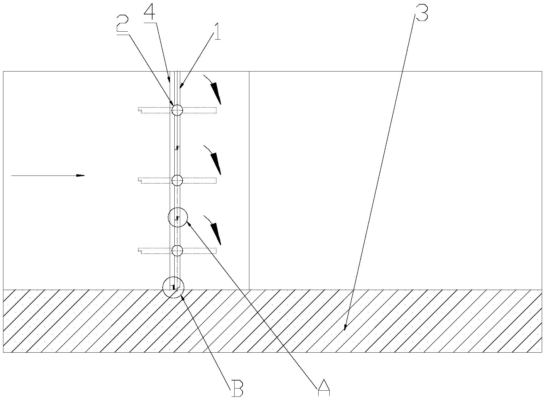
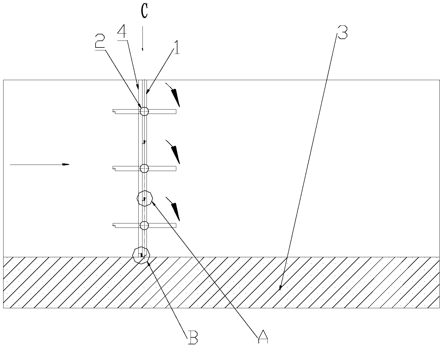
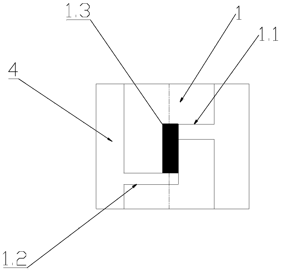
[0026] Such as figure 1 , figure 2 A multi-stage central axis quick flushing door is shown, which includes a plurality of weir plates 1 installed in the conduit 3, and the plurality of weir plates 1 are installed on the vertical surface, and the middle part of each weir plate 1 is connected with a corresponding The rotating shaft 2, in this embodiment, the rotating shaft 2 passes through the longitudinal central axis of the weir plate 1, and the end of the rotating shaft 2 is connected to the output end of the driving device 5, and a second A sealing structure; a second sealing structure is provided at the bottom of the lowermost weir plate.

[0027] In this embodiment, the driving device 5 drives the rotating shaft 2 to rotate, and then drives the weir plate 1 corresponding to the driving shaft 2 to rotate. When each weir plate 1 ...


PUM


Abstract

The invention discloses a multistage middle shaft rapid flushing gate which comprises a plurality of weir plates arranged on a vertical face. The middle part of each weir plate is correspondingly connected with one rotating shaft; the end parts of the rotating shafts are connected with the output end of a driving device; first sealing structures are arranged between the adjacent weir plates; the bottom of the bottommost weir plate is provided with a second sealing structure. The multistage middle shaft rapid flushing gate disclosed by the invention is arranged at an open water gap; the rotating shafts are driven to rotate by the driving device so as to drive the weir plates corresponding to the rotating shafts to rotate; when each weir plate is in a horizontal state, a pipe culvert has the maximum water discharge; when each weir plate rotates to a vertical state, the adjacent weir plates are abutted and are limited by a transverse baffle to form an integrated combined weir plate so as to form the flushing gate for stopping water flow, i.e. the multistage middle shaft rapid flushing gate has an intercepting effect.

Description

technical field [0001] The invention relates to flushing equipment in a drainage system, in particular to a multi-stage center shaft fast flushing door. Background technique [0002] In the drainage system, in order to achieve the purpose of not only controlling the interception flow of water, but also solving the problem of massive discharge of water flow, weir plates are usually used for control. The weir plate is a water-passing structure. When the weir plate is closed and the upstream water level is lower than the top of the weir plate, the water cannot pass through. At this time, the weir plate only has the function of retaining water or intercepting the flow; The intercepted water turns over the top of the weir plate to be discharged; if the upstream water level does not exceed the top of the weir plate and needs to be discharged, open the weir plate, and the upstream water level can be discharged at this time. [0003] In the prior art, the weir plate is mostly an in...

Claims


Application Information

Patent Timeline
Patent Type & Authority Applications(China)
IPC IPC(8): E02B5/08E02B7/46E02B7/54
Inventor 何锐周超
Owner WUHAN SHENGYU DRAINING SYST
Why Eureka
Try Eureka