Porous buffer of hydraulic cylinder

A hydraulic cylinder and buffer technology, applied in the field of hydraulic cylinder buffers, can solve problems such as poor buffering effect and large hydraulic shock, and achieve the effects of small hydraulic shock, stable operation and good buffering effect

Inactive Publication Date: 2014-06-11
WUXI XIEXIN PNEUMATIC
View PDF0 Cites 4 Cited by
  • Summary
  • Abstract
  • Description
  • Claims
  • Application Information

AI Technical Summary

Problems solved by technology

The buffer device generally used is the annular gap buffer. The disadvantages of the traditional annular gap buffer are poor buffering effect and large hydraulic impact.

Method used


Image

  • Porous buffer of hydraulic cylinder

Examples


Embodiment Construction

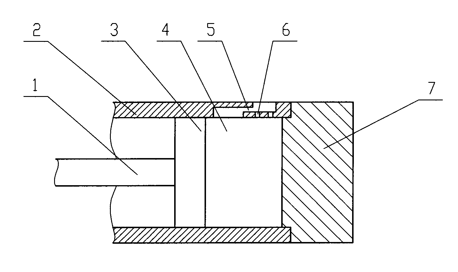
[0009] See figure 1 , the present invention comprises a hydraulic cylinder 2, a piston 3 and a cylinder cover 7 fixedly connected to the hydraulic cylinder 2, the piston 3 is fixedly connected to the piston rod 1, and the side wall of the hydraulic cylinder 2 has a bent orifice 5 and a thin hole 6, and the thin The hole 6 includes a plurality of holes, which respectively communicate with the inner chamber 4 and the orifice 5 of the hydraulic cylinder 2, wherein the purpose of the bent orifice 5 is to further increase the flow resistance of the oil, and the purpose of the thin hole 6 is to act as the inner cavity After the oil pressure in 4 increases to a certain level, the discharge of the oil is accelerated to prevent damage to the hydraulic cylinder 2 caused by excessive internal pressure.

[0010] When the present invention works, when the piston rod 1 moves toward the cylinder head 7 with the piston 3, a buffer oil chamber is formed between the cylinder head 7 and the pist...


PUM


Abstract

The invention relates to a porous buffer of a hydraulic cylinder. The porous buffer of the hydraulic cylinder comprises a hydraulic cylinder, a piston and a cylinder cover fixedly connected to the hydraulic cylinder, and the piston is fixedly connected to a piston rod, wherein the side wall of the hydraulic cylinder comprises a bent throttle orifice and a plurality of pores, and the pores are respectively communicated with an inner cavity of the hydraulic cylinder and the throttle orifice. Compared with the traditional hydraulic cylinder annular throttle buffer, the porous buffer of the hydraulic cylinder provided by the invention has the advantages of good safety, good buffer effect, small hydraulic impact and stable running.

Description

technical field [0001] The invention relates to the field of hydraulic equipment, in particular to a buffer of a hydraulic cylinder. Background technique [0002] When the hydraulic cylinder moves at high speed to the end of the stroke, severe mechanical collisions often occur. In addition, the sudden stop of the piston often causes water hammer in the pipeline, resulting in great impact and noise. The above mechanical shocks not only affect the working performance of mechanical equipment, but also damage hydraulic cylinders and other components of the hydraulic system, which is very dangerous. In order to prevent or reduce this kind of impact vibration, a buffer device is installed inside the hydraulic cylinder, which can play a buffering role to a certain extent. Generally, the buffer device used is an annular throttling buffer. The disadvantages of the traditional annular throttling buffer are poor buffering effect and large hydraulic shock. Contents of the invention ...

Claims


Application Information

Patent Timeline
Patent Type & Authority Applications(China)
IPC IPC(8): F15B15/22
Inventor 陈莉
Owner WUXI XIEXIN PNEUMATIC
Why Eureka
Try Eureka