
Lubricating device of wheel shifting shaft of sterile filling machine

A lubricating device and filling machine technology, applied in the direction of engine lubrication, engine sealing, rigid support of bearing components, etc., can solve the problems of unsatisfactory, difficult to clean and sanitary corners on the table, etc., to ensure cleanliness and reduce sterile space The probability of avoiding the effect of hygienic dead ends

Inactive Publication Date: 2014-06-11
JIANGSU NEWAMSTAR PACKAGING MACHINERY
View PDF6 Cites 0 Cited by
  • Summary
  • Abstract
  • Description
  • Claims
  • Application Information

AI Technical Summary

Problems solved by technology

The lower bearing is lubricated in the external environment, so it is very easy to lubricate, while the upper bearing is lubricated by fixing an oil pipe directly above the frame. The oil pipe is directly connected to the top of the bearing sleeve, so that there is a sanitary dead corner that is difficult to clean on the table, which cannot meet the requirements. In some aseptic filling fields

Method used


Image

  • Lubricating device of wheel shifting shaft of sterile filling machine
  • Lubricating device of wheel shifting shaft of sterile filling machine

Examples


Embodiment Construction

[0016] The present invention will be described in further detail below through specific examples.

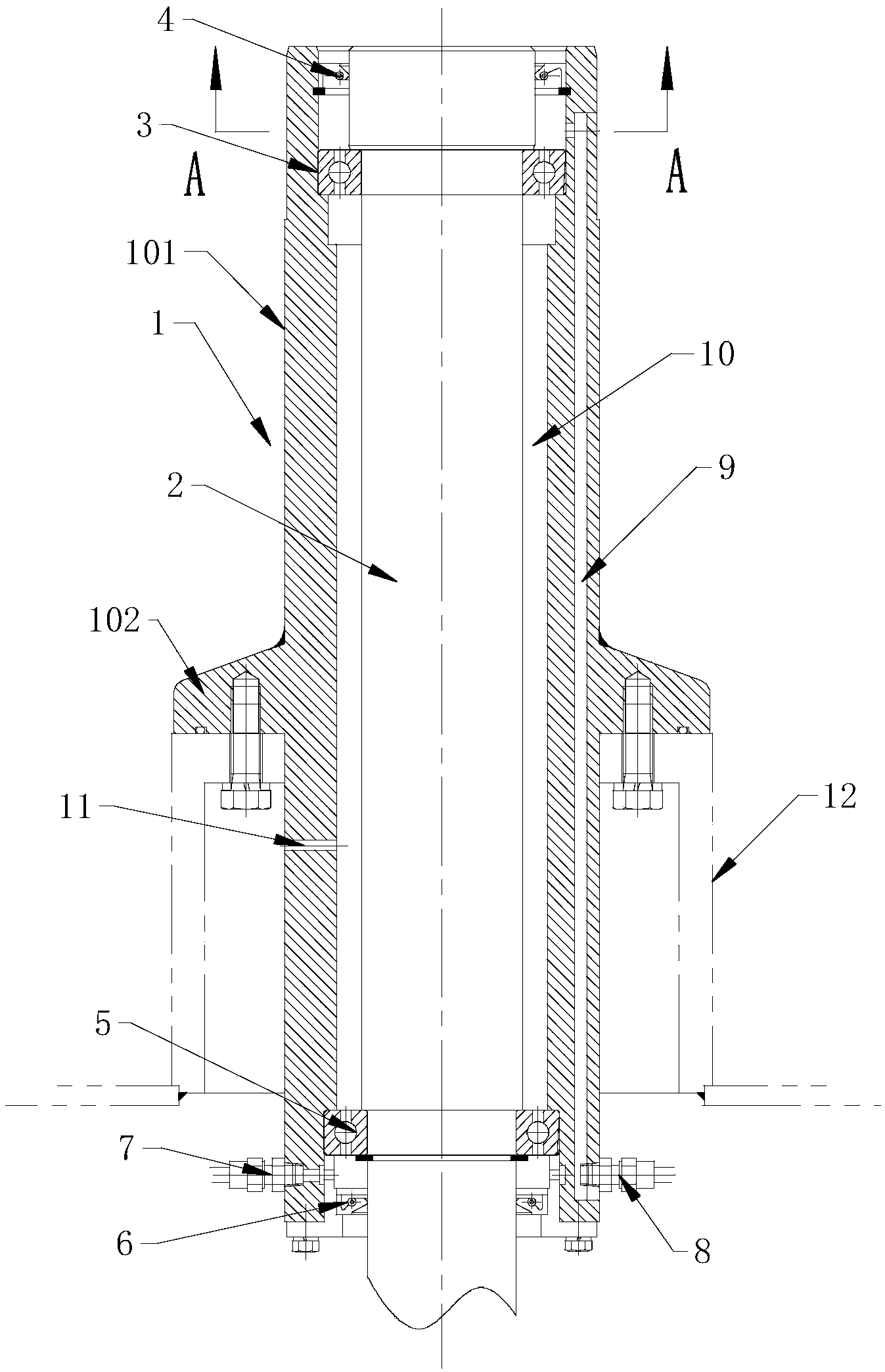
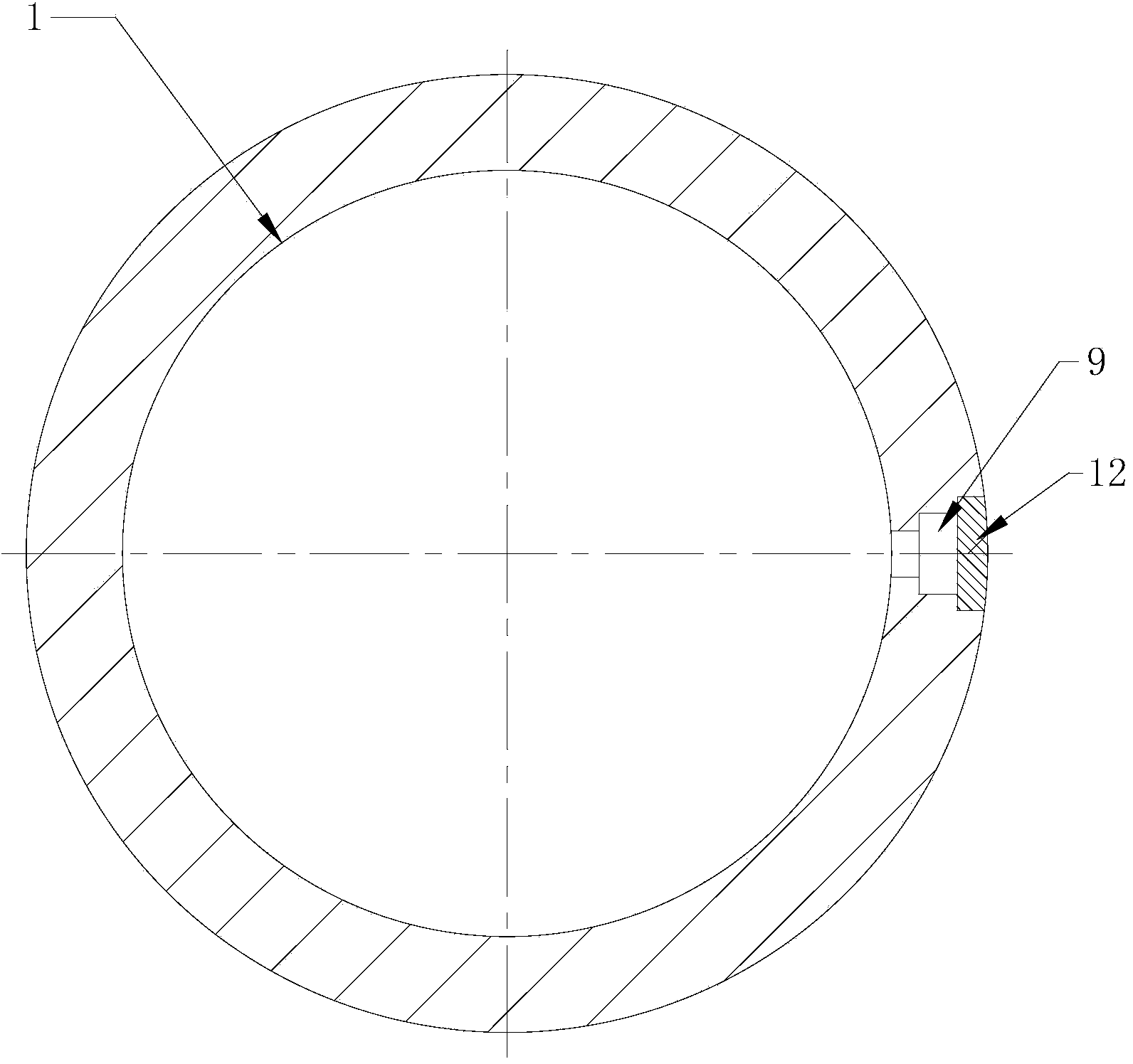
[0017] Such as figure 1 , 2 As shown, a lubricating device for the dial shaft 2 of an aseptic filling machine, the dial is installed in the bearing sleeve 1 through the rotation of the upper end bearing 3 and the lower end bearing 5, and the bearing sleeve 1 penetrates and is fixed on the frame; The upper end and the lower end of the dial shaft 2 cooperate with the bearing sleeve 1 through the upper seal ring 4 and the lower seal ring 6 respectively; the upper seal ring 4 and the lower seal ring 6 seal the gap between the dial shaft 2 and the bearing sleeve 1 into The lubricating chamber 10, the upper end bearing 3 and the lower end bearing 5 are located in the lubricating chamber 10; the lower end of the bearing sleeve 1 is provided with a lower lubricating port connected to the lower lubricating oil passage 7, and an upper lubricating port connected to the upper lubricating o...


PUM


Abstract

The invention discloses a lubricating device of a wheel shifting shaft of a sterile filling machine. A shifting wheel is rotationally arranged inside a bearing sleeve through an upper end bearing and a lower end bearing; the bearing sleeve penetrates through and is fixed on a frame; the upper end and the lower end of the wheel shifting shaft are respectively matched with the bearing sleeve through an upper sealing ring and a lower sealing ring; a clearance between the wheel shifting shaft and the bearing sleeve is sealed to form a lubricating cavity by the upper sealing and the lower sealing ring; the upper end bearing and the lower end bearing are arranged inside the lubricating cavity; a lower lubricating opening communicated with a lower lubricating oil way, and an upper lubricating opening communicated with an upper lubricating oil way are formed in the lower end of the bearing sleeve; the lower lubricating opening is communicated with the lubricating cavity between the lower end bearing and the lower sealing ring; the upper lubricating opening is communicated with the lubricating cavity between the upper end bearing and the upper sealing ring through an axial slideway arranged on the sleeve wall of the bearing sleeve; a vent hole communicated with the lubricating cavity is formed in the bearing sleeve. The lubricating device is simple in structure, and free of a dusty corner, and a table board of the frame is concise and clean on the premise of ensuring full lubrication of the upper end bearing.

Description

technical field [0001] The invention relates to a lubricating device, in particular to a lubricating device for a dial shaft of an aseptic filling machine. Background technique [0002] The two ends of the dial shaft of the aseptic filling machine are installed in a bearing sleeve through bearing rotation, and the bearing sleeve is fixed on the frame and runs through the frame; above the frame is a sterile space. The upper and lower end bearings of the dial shaft need to be lubricated. The lower bearing is lubricated in the external environment, so it is very easy to lubricate, while the upper bearing is lubricated by fixing an oil pipe directly above the frame. The oil pipe is directly connected to the top of the bearing sleeve, so that there is a sanitary dead corner that is difficult to clean on the table, which cannot meet the requirements. Some aseptic filling fields. Contents of the invention [0003] The technical problem to be solved by the present invention is t...

Claims


Application Information

Patent Timeline
Patent Type & Authority Applications(China)
IPC IPC(8): F16C35/12F16N1/00F16J15/16
Inventor 王晶邹中全
Owner JIANGSU NEWAMSTAR PACKAGING MACHINERY
Learn More