
Self-closing water saving valve

A self-closing, water-saving valve technology, applied in the direction of valve details, valve devices, functional valve types, etc., can solve the problems of short time for water outflow, damage to noisy water pipes, wear and tear of time control gasket 93, etc., to achieve convenient push and open , Reduce violent vibration, avoid water hammer sound and water pipe damage

Active Publication Date: 2016-05-11
NEOPERL INT
View PDF6 Cites 0 Cited by
  • Summary
  • Abstract
  • Description
  • Claims
  • Application Information

AI Technical Summary

Problems solved by technology

[0007] First, when in use, when the water stop gasket 94 plugs the water inlet 911 to close the water flow, the water flowing in the water pipe cannot continue to flow because it suddenly hits the closed water inlet 911, and then a series of positive and negative pressure waves are generated. Vibrating back and forth in the water pipe until the energy stops due to friction, this phenomenon will cause harsh noise and may cause damage to the water pipe, and the harsh noise is water hammer sound; in addition, when the user pushes the control lever 92 upwards to When the water flow is turned on, since the top of the control rod 92 and the water stop washer 94 must resist the water pressure generated by the water flow in the water pipe, the hand feeling is not smooth in operation.
[0008] Its two, because every time it is closed, the time control washer 93 will rub against the inner wall of the time control passage 913, so after a period of use, the time control washer 93 may wear and cause the outer diameter to gradually shrink, and thus reduce the contact with the time control channel 913. The friction force on the inner wall surface of the time control channel 913 causes the control rod 92 to descend faster and faster, and the time for the water flow to flow out becomes shorter and shorter

Method used


Image

  • Self-closing water saving valve
  • Self-closing water saving valve
  • Self-closing water saving valve

Examples


Embodiment Construction

[0079] The technical means adopted by the present invention to achieve the intended invention purpose are further described below in conjunction with the drawings and preferred embodiments of the present invention.

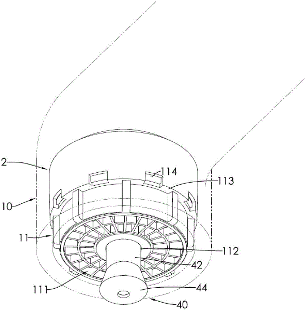
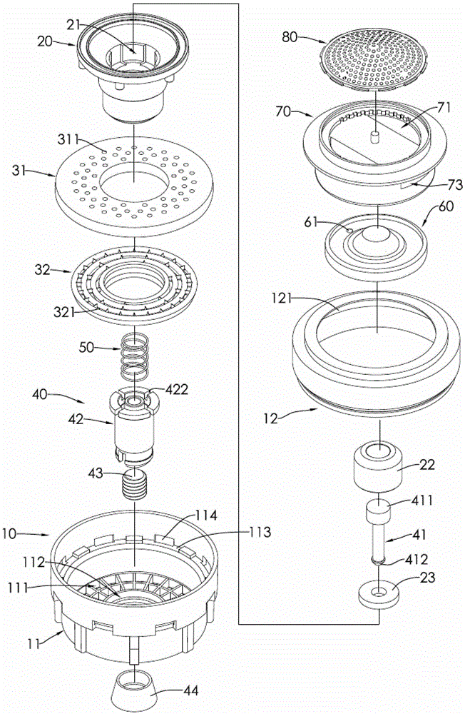
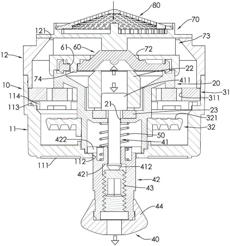
[0080] see figure 1 and figure 2 As shown, the self-closing water saving valve of the present invention includes a housing 10, a seat 20, a control rod 40, a sleeve 60 and a water inlet seat 70; in this embodiment, it further includes a valve seat 31 , a water outlet grid frame 32 , an elastic element 50 and a filter screen cover 80 .

[0081] see Figure 1 to Figure 3 As shown, the aforementioned housing 10 includes a base 11 and an upper cover 12, the base 11 and the upper cover 12 cover an inner space; the base 11 is provided with a water outlet 111 and a housing rod hole 112, and the water outlet 111 surrounds The housing rod hole 112, and the water outlet 111 is in the shape of a radial grid; the wall surface of the base 11 is in a step shape and has a s...


PUM


Abstract

The invention provides an automatic closing water-saving valve arranged on a faucet. The automatic closing water-saving valve comprises a shell, a bearing, a control rod, a sleeve part and a water inlet seat. When the automatic closing water-saving valve is opened, the control rod can slowly move down due to gravity and a slight water pressure until an upper abut-against part of the control rod seals up a bearing rod hole; then water flowing into a space between the bearing and the sleeve part from a sleeve hole of the sleeve part is gradually accumulated to squeeze the sleeve part upwards and enable the sleeve part to be deformed, so that the sleeve part seals up the water inlet seat to stop the water flow, and thus, an automatic closing effect is achieved. The deformation process of the sleeve part is progressive, and thus, the sleeve part has an effect of buffering to turn off water, so that water hammer sound is avoided. Moreover, the water pressure is not directly acted to the control rod, and thus, a force which needs to be applied when the control rod is operated is small.

Description

technical field [0001] The invention relates to a self-closing water-saving valve installed on a water tap. Background technique [0002] The water pipe control valve in the prior art is installed at the switch on the faucet, which has the advantage of simple structure. However, after people finish washing, they must lift their hands to operate the control valve located above the water pipe faucet. Action will cause the waste of water resources at the same time. [0003] In order to solve the aforementioned problem of wasting water resources, relevant technical personnel have developed an infrared sensor water valve. When people perform washing actions, they can place their hands in the sensing area, and the water valve can be opened through infrared induction; completed After the hand is removed during the washing action, the water valve will automatically close, thereby achieving the effect of saving water; but because the infrared sensing range is a specific area, people...

Claims


Application Information

Patent Timeline
Patent Type & Authority Patents(China)
IPC IPC(8): F16K21/06
CPCF16K21/06F16K47/023
Inventor 高志宏萧钦元
Owner NEOPERL INT
Learn More