
airport taxiway edge lights

A taxiway and airport technology, which is applied to the damage prevention measures of lighting devices, lighting applications, lighting and heating equipment, etc., can solve the hidden dangers of airport aircraft safety, can not take into account the role of taxiway edge lights and taxiway reflective sign bars, Increase the unsafe factors of aircraft on the airport taxiway to achieve the effect of simple structure and avoid working all the time

Active Publication Date: 2016-10-19
SHENZHEN OCEANS KING LIGHTING ENG CO LTD +1
View PDF3 Cites 0 Cited by
  • Summary
  • Abstract
  • Description
  • Claims
  • Application Information

AI Technical Summary

Problems solved by technology

For the sake of energy saving, many airports will use a certain number of taxiway retroreflective marking sticks to replace the vertical taxiway edge lights, but this practice has certain hidden dangers to the safety of airport aircraft operations. , the outer boundary of the taxiway can be marked with taxiway retroreflective marking sticks
However, under severe weather conditions, such as rainy and snowy days, light foggy weather and other weather conditions with poor visibility, the taxiway reflective sign sticks cannot play their due role, and in severe cases, it will affect the safety of aircraft operating on the taxiway
The shortcomings of the vertical taxiway edge lights and taxiway retroreflective marking sticks under the current situation are that they cannot take into account the functions of taxiway edge lights and taxiway reflective marking sticks
If the taxiway retro-reflective sign stick is used, it will increase the unsafe factors of airport taxiway aircraft operation in bad weather

Method used


Image

  • airport taxiway edge lights
  • airport taxiway edge lights
  • airport taxiway edge lights

Examples


Embodiment Construction

[0029] In order to facilitate the understanding of the present invention, the present invention will be described more fully below with reference to the associated drawings. Preferred embodiments of the invention are shown in the accompanying drawings. However, the present invention can be embodied in many different forms and is not limited to the embodiments described herein. On the contrary, these embodiments are provided to make the understanding of the disclosure of the present invention more thorough and comprehensive.

[0030] It should be noted that when an element is referred to as being “fixed” to another element, it can be directly on the other element or there can also be an intervening element. When an element is referred to as being "connected to" another element, it can be directly connected to the other element or intervening elements may also be present. The terms "vertical," "horizontal," "left," "right," and similar expressions are used herein for purposes ...


PUM


Abstract

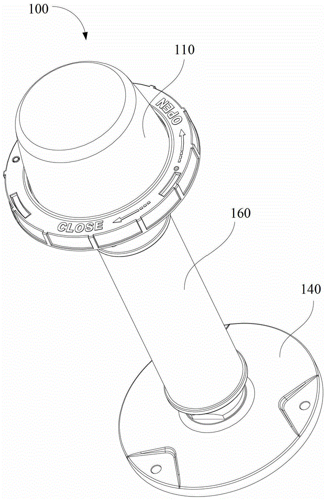
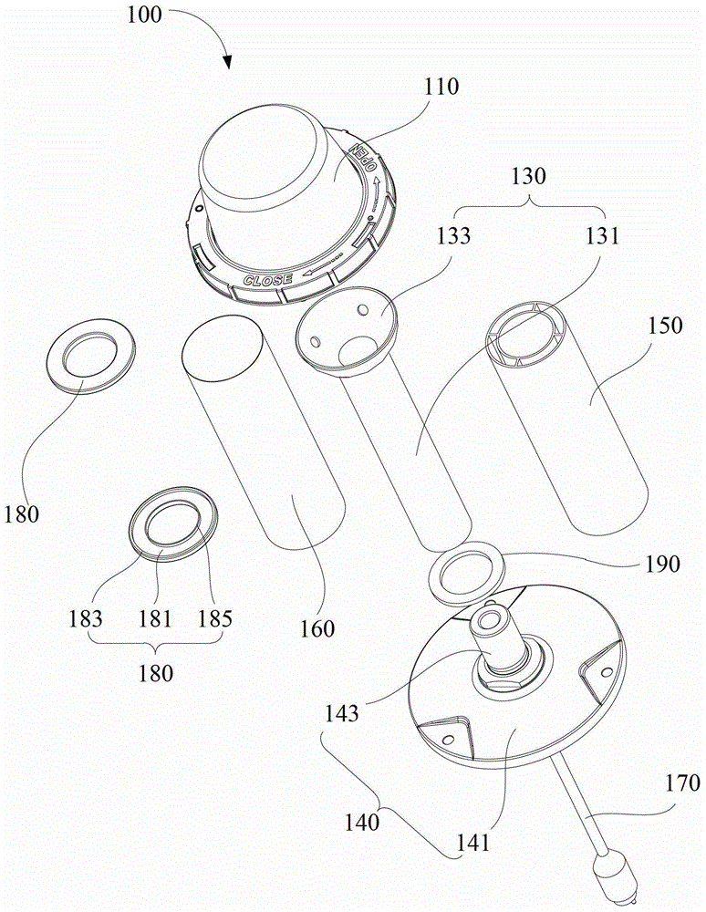
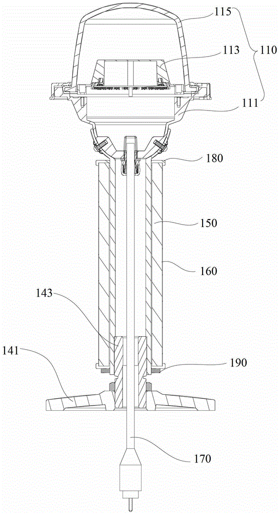
Disclosed is an airport sliding ramp side lamp. The airport sliding ramp side lamp comprises an LED (light emitting diode) lamp cap assembly which can emit all-around light, a support unit with one end fixedly connected with the bottom of the LED lamp cap assembly and used for supporting the LED lamp cap assembly, a base assembly which is fixedly connected with the other end of the support unit, a reflective bar body which is of a hollow structure and sleeves the support unit, and a reflecting barrel sleeving the reflective bar body, wherein the LED lamp cap assembly is vertically arranged above the base assembly through the support unit. According to the airport sliding ramp side lamp, the LED lamp cap assembly is supported by the support unit, a reflective bar is composed of the reflective bar body sleeving the support unit and the reflecting barrel, so that the LED lamp cap assembly can be used in poor-visibility weather conditions, and when in high-visibility weather conditions, only the reflective bar is utilized, further the LED lamp cap assembly can avoid working all the time; meanwhile, in the poor-visibility weather conditions, the reflective bar can also play a role of auxiliary indication. Therefore, the airport sliding ramp side lamp is simple in structure, relatively energy-saving, safe and reliable.

Description

【Technical field】 [0001] The invention relates to an airport lamp, in particular to an airport taxiway edge lamp. 【Background technique】 [0002] At present, the taxiway lighting system of each airport uses vertical taxiway edge lights and taxiway retro-reflective sign sticks to mark the airport taxiway boundary. The vertical taxiway edge lights and taxiway retro-reflective sign sticks have the same function and can be complement each other under certain conditions. For the sake of energy saving, many airports will use a certain number of taxiway retroreflective marking sticks to replace the vertical taxiway edge lights, but this practice has certain hidden dangers to the safety of airport aircraft operations. , the outer boundary of the taxiway may be marked with taxiway retroreflective marking sticks. However, under severe weather conditions, such as rainy and snowy days, light foggy weather and other weather conditions with poor visibility, the taxiway reflective markin...

Claims


Application Information

Patent Timeline
Patent Type & Authority Patents(China)
IPC IPC(8): F21S8/00F21V7/22F21V17/12F21V15/00F21W111/06F21Y115/10
Inventor 周明杰姜涛
Owner SHENZHEN OCEANS KING LIGHTING ENG CO LTD
Learn More