Centralized MIMO (Multiple Input Multiple Output) radar waveform designing method based on receiving wave beam formation

A radar waveform and receiving beam technology, applied in the radar field, can solve the problem of reducing the distance side lobe and angle side lobe of the received echo of the centralized MIMO radar, reducing the detection performance of the centralized MIMO radar, high distance side lobe and angle side lobe, etc. question

Active Publication Date: 2014-06-11
XIDIAN UNIV
View PDF4 Cites 23 Cited by
  • Summary
  • Abstract
  • Description
  • Claims
  • Application Information

AI Technical Summary

Problems solved by technology

However, the above methods only consider the factor of approaching the desired transmission pattern. In practice, not only the designed MIMO radar waveform is required to have the desired transmission pattern, but also the designed MIMO radar waveform is required to reduce the reception of the centralized MIMO radar. Distance sidelobe and angle sidelobe of echo
Therefore, the MIMO radar waveform designed by the existing method causes the centralized MIMO radar to receive echoes with too high range sidelobes and angle sidelobes, which reduces the detection performance of the centralized MIMO radar

Method used


Image

  • Centralized MIMO (Multiple Input Multiple Output) radar waveform designing method based on receiving wave beam formation
  • Centralized MIMO (Multiple Input Multiple Output) radar waveform designing method based on receiving wave beam formation
  • Centralized MIMO (Multiple Input Multiple Output) radar waveform designing method based on receiving wave beam formation

Examples


Embodiment Construction

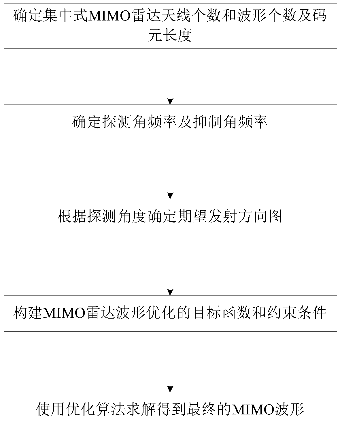
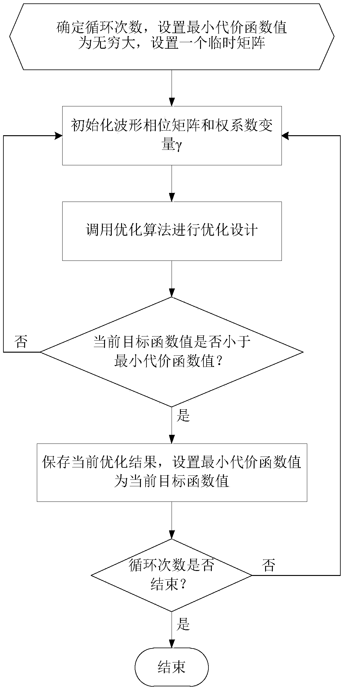
[0023] refer to figure 1 , the implementation steps of the present invention are as follows:

[0024] Step 1, determine the number of centralized MIMO radar antennas and the number and length of MIMO radar waveforms.

[0025] In the present invention, since the transmitting beamforming and receiving beamforming are used in the waveform design process, it is necessary to determine the number of transmitting antennas and the number of receiving antennas of the centralized MIMO radar. And the present invention requires that both the transmitting antenna array and the receiving antenna array are uniform linear arrays with a half-wave spacing. For a given centralized MIMO radar system, the number of transmit antennas and receive antennas is known.

[0026] According to the actual centralized MIMO radar system, the number of transmitting antennas N is obtained t and the number of receiving antennas N r ;

[0027] According to the number of MIMO radar waveforms is equal to the n...


PUM


Abstract

The invention discloses a centralized MIMO (Multiple Input Multiple Output) radar waveform designing method based on receiving wave beam formation and mainly solves the problem that the existing method is incapable of reducing a receiving echo distance sidelobe and an angle sidelobe of the centralized MIMO radar. The Centralized MIMO radar waveform designing method comprises the following steps: (1), determining the number of antennas, the number of waveforms and lengths of code elements of the centralized MIMO radar according to an actual radar system and requirement; (2), determining a detection angle and an inhibition angle according to radar detection requirement and normalizing the detection angle and the inhibition angle; (3), determining an expected sending direction map according to the detection angle; (4), building a target function and constraint conditions for optimizing the MIMO radar waveform; and (5), obtaining the MIMO radar waveform by an optimization algorithm according to the built target function and the constraint conditions. The centralized MIMO radar waveform designing method is capable of reducing the receiving echo distance sidelobe and the angle sidelobe of the centralized MIMO radar and can be used for designing the waveform of the centralized MIMO radar.

Description

technical field [0001] The invention belongs to the technical field of radar, and specifically relates to a MIMO radar waveform design method, which is used for reducing the distance sidelobe and angle sidelobe of the echo received by the centralized MIMO radar, and approaching the desired emission pattern. Background technique [0002] MIMO radar is a new active detection technology, and has become a research hotspot in the field of radar technology. According to the distance between the transmitting antenna and the receiving antenna, MIMO radar can be divided into two types: distributed MIMO radar and centralized MIMO radar. For the centralized MIMO radar, its characteristic is that the distance between the transmitting and receiving antennas or array elements is relatively small. Compared with phased array radar, centralized MIMO radar has the ability to freely design the signal waveform of each array element, so it has higher resolution for space targets, better sensiti...

Claims


Application Information

Patent Timeline
Patent Type & Authority Applications(China)
IPC IPC(8): G01S7/02
CPCG01S7/2813
Inventor 刘宏伟周生华臧会凯纠博王旭
Owner XIDIAN UNIV
Why Eureka
Try Eureka