Workpiece locating system, loading system and plasma processing device

A technology for positioning systems and workpieces, applied in the direction of electrical components, conveyor objects, transportation and packaging, etc., can solve the problems of taking out workpieces, position deviation, and reducing the transmission efficiency of the loading system, so as to improve the transmission efficiency and process efficiency. Effect

Active Publication Date: 2014-06-11
BEIJING NAURA MICROELECTRONICS EQUIP CO LTD
View PDF4 Cites 4 Cited by
  • Summary
  • Abstract
  • Description
  • Claims
  • Application Information

AI Technical Summary

Problems solved by technology

[0004] The above-mentioned loading system inevitably has the following problems in practical applications, that is, in the process of transporting the workpiece 8 by the workpiece conveyor belt 4, because it needs to transport the workpiece 8 to the corresponding standard pick-up position at high speed and make an emergency stop, for example, in the During the process of transporting the above-mentioned first piece of workpiece 8 from the standard release position 7 to the standard take-up position D, the workpiece conveyer belt 4 has carried out four emergency stops, which will cause the workpiece 8 to be stopped due to the emergency stop of the workpiece conveyer belt 4. Self-inertia produces relative slippage with the workpiece conveyor belt 4, that is, the actual position of the workpiece 8 on the workpiece c

Method used


Image

  • Workpiece locating system, loading system and plasma processing device
  • Workpiece locating system, loading system and plasma processing device
  • Workpiece locating system, loading system and plasma processing device

Examples


Example Embodiment

[0027] To enable those skilled in the art to better understand the technical solutions of the present invention, the workpiece positioning system, loading system and plasma processing equipment provided by the present invention will be described in detail below with reference to the accompanying drawings.
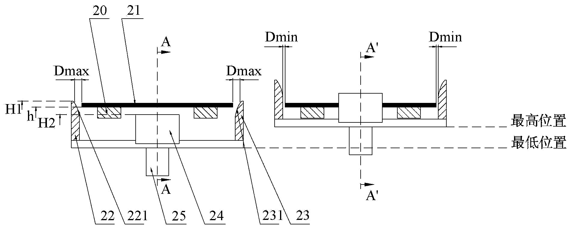
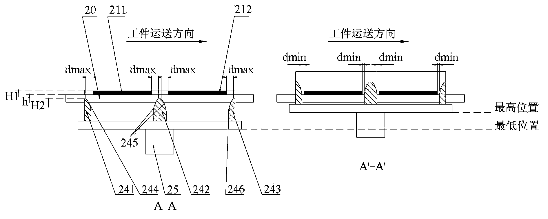
[0028] Figure 2a It is a cross-sectional view of the workpiece positioning system provided by the first embodiment of the present invention. Figure 2b for Figure 2a A cross-sectional view taken along line A-A and line A'-A'. Figure 2c It is a top view of the workpiece positioning system provided by the first embodiment of the present invention. Please refer to Figure 2a , Figure 2b with Figure 2c , The workpiece positioning system includes a workpiece conveyor 20 and a position calibration device. Among them, the workpiece conveying belt 20 is two parallel and spaced strip conveying belts, and on the workpiece conveying belt 20, along the conveying direction of the workp...


PUM


Abstract

The invention provides a workpiece locating system, a loading system and a plasma processing device. The workpiece locating system comprises two workpiece conveying belts which are arranged in parallel in a spaced mode. The workpiece conveying belts are sequentially divided into a standard sheet placing position and N standard sheet taking positions in the workpiece conveying direction, wherein N is an integer larger than zero. The standard sheet placing position is a sheet placing position where workpieces can be placed on the workpiece conveying belts, wherein the standard sheet placing position is preset on the workpiece conveying belts. The standard sheet taking positions are sheet taking positions where the workpieces can be taken out of the workpiece conveying belts, wherein the standard sheet taking positions are preset on the workpiece conveying belts. The workpiece locating system further comprises a position calibration device which is used for calibrating the positions of the workpieces on the workpiece conveying belts in the two-dimensional direction, so that the positional deviation between each workpiece and the corresponding standard sheet taking position is calibrated. The positional deviation between each workpiece on the workpiece conveying belts and the corresponding standard sheet taking position can be automatically calibrated through the loading system, so that the transmission efficiency is high, and the technical efficiency of the plasma processing device is improved.

Description

technical field [0001] The invention relates to the technical field of semiconductor equipment manufacturing, in particular to a workpiece positioning system, a loading system and plasma processing equipment. Background technique [0002] In the semiconductor equipment manufacturing industry, in order to improve production efficiency, when producing products such as integrated circuits, liquid crystal displays, thin-film solar cells, and LEDs, it is usually necessary to transfer dozens or even hundreds of workpieces to large-size carrier plates by means of a loading system. Then the carrier plate is sequentially transferred to various chambers for implementing different processes, so as to realize the processing of multiple workpieces within one process cycle. [0003] figure 1 A top view of the existing loading system. Such as figure 1 As shown, the loading system includes a loading platform 1 , a manipulator 3 , a workpiece conveyor belt 4 , a gantry 5 and a carrier pla...

Claims


Application Information

Patent Timeline
IPC IPC(8): H01L21/68H01L21/677H01J37/32
CPCH01J37/32H01L21/67754H01L21/68
Inventor 杨斌
Owner BEIJING NAURA MICROELECTRONICS EQUIP CO LTD
Why Eureka
Try Eureka