Converter cooling lines and cooling units

A technology for cooling pipelines and converters, which is applied in the direction of output power conversion devices, cooling/ventilation/heating transformation, electrical components, etc. Uniformity and other issues to achieve the effect of improving heat dissipation balance and cooling effect, flow balance, and reducing installation space

Active Publication Date: 2016-06-15
CRRC YONGJI ELECTRIC CO LTD
View PDF3 Cites 4 Cited by
  • Summary
  • Abstract
  • Description
  • Claims
  • Application Information

AI Technical Summary

Problems solved by technology

[0006] The present invention provides a converter cooling pipeline and a cooling device, which are used to solve the problems in the prior art that the converter cooling pipeline has a complex structure, takes up a large space, and is unevenly distributed when it is applied to a large number of power modules. technical flaw

Method used


Image

  • Converter cooling lines and cooling units
  • Converter cooling lines and cooling units
  • Converter cooling lines and cooling units

Examples


Embodiment Construction

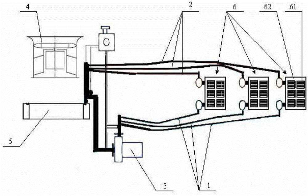
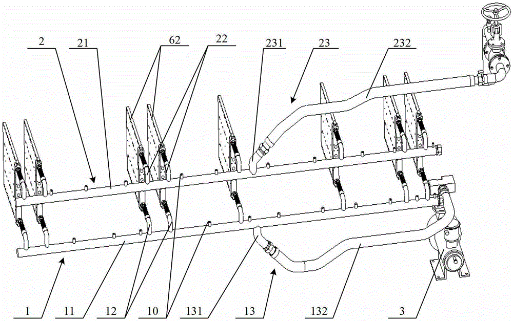
[0032] refer to Figure 2~4 , figure 2 A schematic diagram of the converter cooling pipeline provided by the embodiment of the present invention; image 3 for figure 2 The schematic diagram of the water inlet pipeline in ; Figure 4 for figure 2 Schematic diagram of the outlet pipeline in .

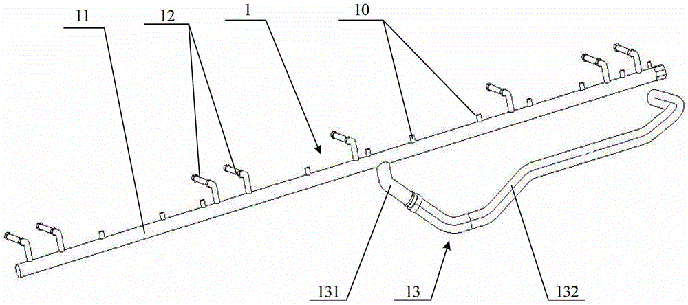
[0033] Such as Figure 2~4 As shown, the converter cooling pipeline provided in this embodiment includes a water inlet pipeline 1 and a water outlet pipeline 2 .

[0034] The water inlet pipeline 1 includes a water inlet main pipe 11 and a plurality of water inlet pipes 12; the water inlet main pipe 11 is used to communicate with the water outlet of the water pump 3; The other end of 12 is used to communicate with the water inlet of the water-cooled substrate 62 of the power module.

[0035] The water outlet pipeline 2 includes a water outlet main pipe 21 and a plurality of water outlet pipes 22; the water outlet main pipe 21 is used to communicate with the water inlet of the he...


PUM


Abstract

A cooling pipeline and cooling apparatus for a converter. The cooling pipeline comprises a water inlet pipeline (1) and a water outlet pipeline (2). The water inlet pipeline comprises a water inlet main pipe (11) and a plurality of water inlet branch pipes (12). The water inlet main pipe is connected to a water pump (3). One end of the plurality of water inlet branch pipes is connected to the water inlet main pipe, and the other end of the plurality of water inlet branch pipes is connected to a water inlet opening of a water cooling substrate (62) for a power module of the converter. The water outlet pipeline comprises a water outlet main pipe (21) and a plurality of water outlet branch pipes (22). The water outlet main pipe is connected to a heat exchanger. One end of the plurality of water outlet branch pipes is connected to the water outlet main pipe, and the other end of the plurality of water outlet branch pipes is connected to a water outlet opening of the water cooling substrate for the power module of the converter. By designing a structure of a fitting main pipe and branch pipe for a water inlet pipeline and a water outlet pipeline, the number of pipelines can be reduced and the complexity of pipeline can be lowered, and also the installation space occupied by the pipelines can be reduced.

Description

technical field [0001] The invention relates to high-power converter technology, in particular to a converter cooling pipeline and a cooling device. Background technique [0002] High-power converter is one of the important components of AC drive system of electric locomotive. When the electric locomotive is running normally, the power device of the high-power converter realizes the conduction and shutdown of the circuit. The power device can be an insulated gate bipolar transistor (Insulated Gate Bipolar Transistor, referred to as IGBT) device or a semiconductor device such as a diode. When the power device is working The generated energy loss appears in the form of heat. If the heat generated by the power devices cannot be dissipated in a timely and effective manner, the working efficiency of the high-power converter will be affected, and the high-power converter may even fail to work. Therefore, appropriate cooling methods must be used to take away the heat generated by ...

Claims


Application Information

Patent Timeline
Patent Type & Authority Patents(China)
IPC IPC(8): H02M1/00H05K7/20
CPCH05K7/20927
Inventor 姬慧刚王彬刘佳姜新生
Owner CRRC YONGJI ELECTRIC CO LTD
Why Eureka
Try Eureka