

Busbar connection
A busbar connection and busbar technology, applied in the direction of connection, connecting device components, butt-jointing busbars, etc., can solve the problems of expensive manufacturing steps, high cost, etc., and achieve the effect of peak reduction
- Summary
- Abstract
- Description
- Claims
- Application Information
AI Technical Summary
Problems solved by technology
Method used
Image

Examples
Embodiment Construction
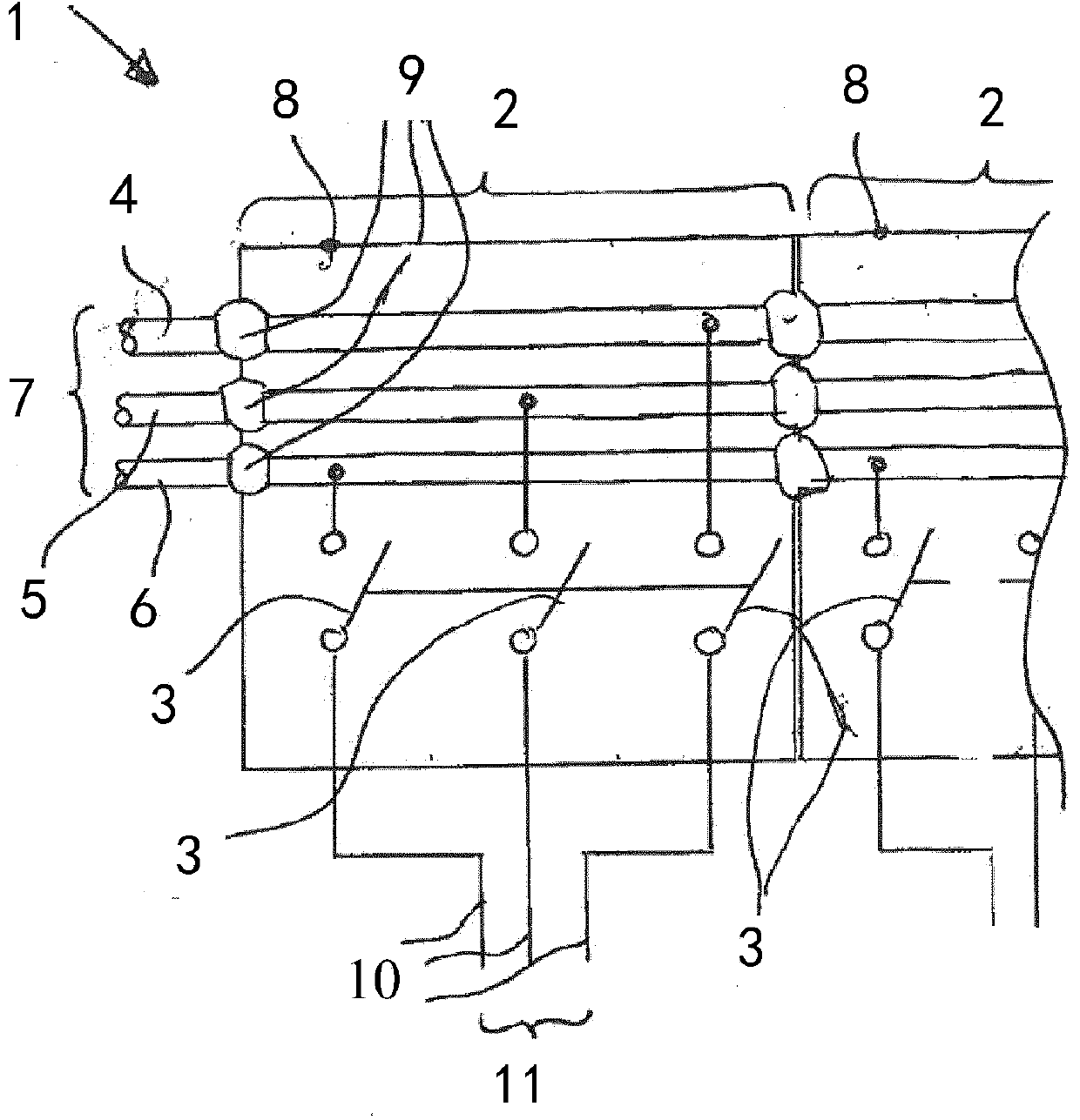
[0028] figure 1 A schematic diagram of a switchgear 1 typically used in medium and high voltage applications is shown. The switchgear has two panels 2 each with three switches 3 arranged in a housing 8 .
[0029] Three busbars 4 , 5 and 6 run through each housing 8 and there is a busbar connection 9 at each transition from one housing 8 to the next. Each switch 3 of the panel 2 connects one of the busbars 4 , 5 and 6 to one of the lines 10 of the subnetwork 11 to be able to switch the subnetwork 11 on or off from the mains 7 .
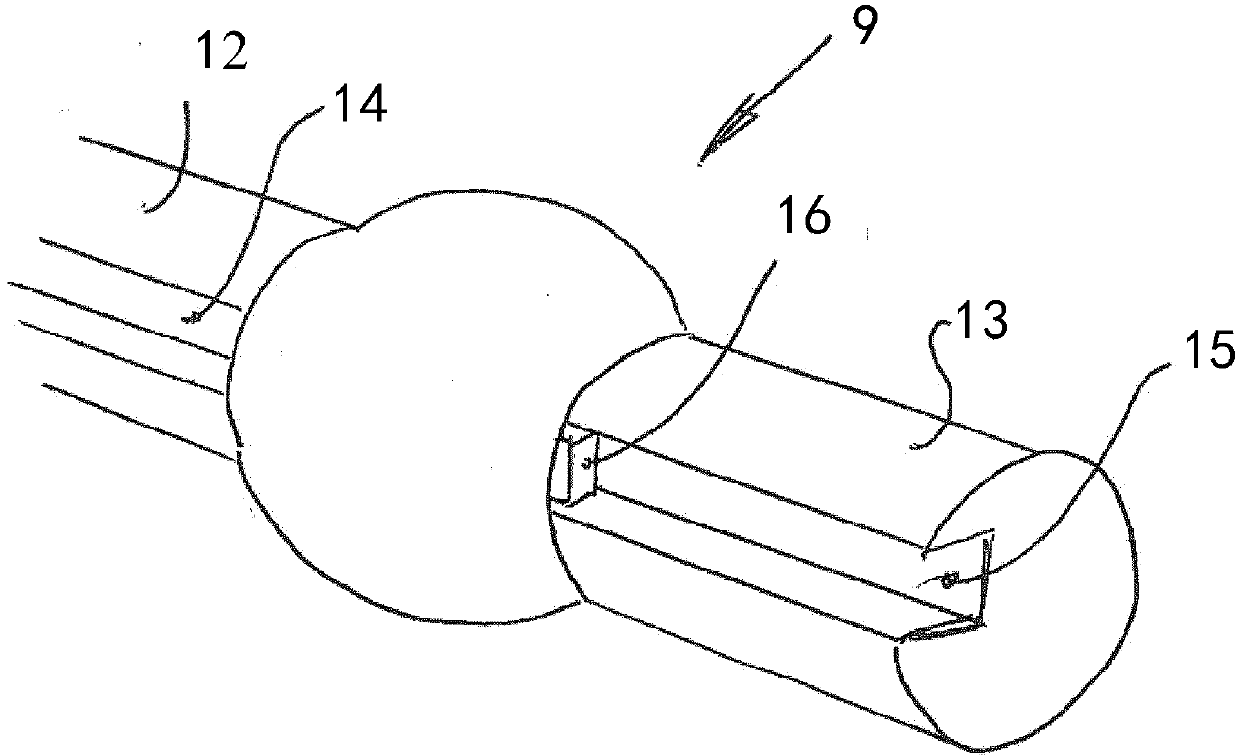
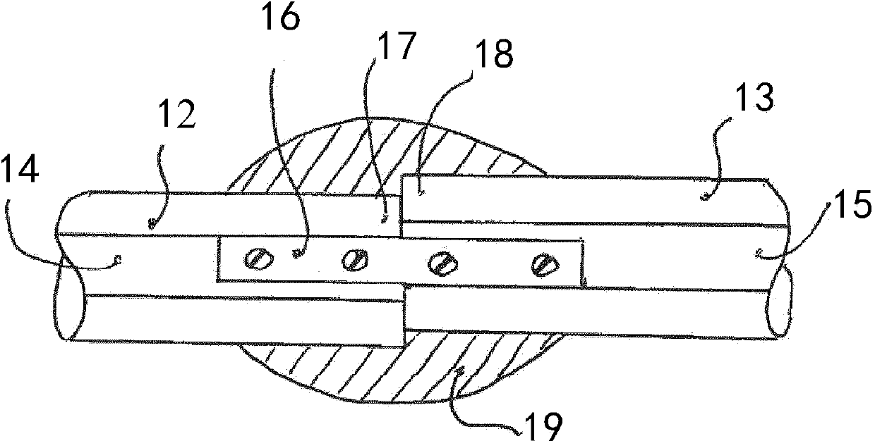
[0030] figure 2 A perspective view of a busbar connection according to the invention is shown. The two busbar parts 12 and 13 are placed adjacently, but not necessarily aligned. Each busbar part 12, 13 has a slot 14, 15 in which a conductor 16 is placed. The conductor 16 ensures a solid connection between the two busbar parts 12 and 13 (see also image 3 ).
[0031] image 3 The respective free ends 17 , 18 of the busbar parts 12 , 13 are show...
PUM
 Abstract
Description
Claims
Application Information