

Apple bagging mechanism
A technology of bagging and apples, applied in the direction of plant protection covers, etc., can solve the problems of imperfect technology, time-consuming, laborious, tedious and tiring, etc., and achieve the effect of simple sealing, precise position and reliable control
- Summary
- Abstract
- Description
- Claims
- Application Information
AI Technical Summary
Problems solved by technology
Method used
Image

Examples
Embodiment Construction
[0035] The present invention will be described in further detail below in conjunction with the accompanying drawings.
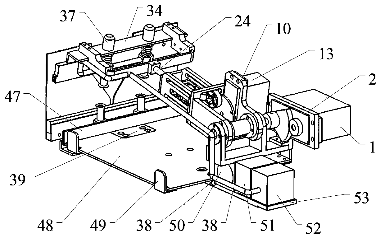
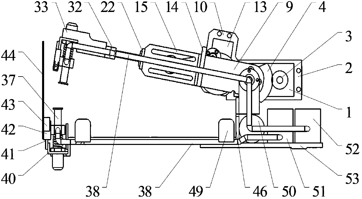
[0036] Such as figure 1 , figure 2As shown, the whole of the present invention is installed on the mechanical arm by mechanically connecting the bottom plate 53, including a fruit bag device, a pitching device, a telescopic device, an upper sticky bag device, a lower sticky bag device and an air suction device, wherein the fruit bag device and the suction machine The air device is directly fixed on the mechanical arm connection base plate 53 respectively, the pitching device is installed on the fruit bag device, the telescopic device is connected with the pitching device, and is driven by the pitching device to swing around the pitching support shaft 5; the upper sticking bag device is connected to The output end of the telescopic device is driven to expand and contract by the telescopic device, and together with the telescopic device, it swings around the ...
PUM
 Abstract
Description
Claims
Application Information