Liquid supply device with central shaft with electroplating coating and buffer limit pipe section

A technology of electroplating coating and central shaft, which is applied in the direction of liquid spraying device, spraying device, cleaning method and utensils, and can solve the problems of not having regular manual maintenance

Active Publication Date: 2015-11-18
无锡丰荣电镀设备制造有限公司
View PDF8 Cites 0 Cited by
  • Summary
  • Abstract
  • Description
  • Claims
  • Application Information

AI Technical Summary

Problems solved by technology

However, in some cases, such as the maintenance of urban lawns, devices that use air pressure to deliver liquid need to draw liquid streams from some alternate liquid source, such as recycled rainwater, greywater, or even untreated ground surface Runoff water, and these devices that use air pressure to give liquid do not have the conditions for regular manual maintenance. Therefore, in this case, it is urgent to remove impurities to ensure the normal operation of the device that uses air pressure to give liquid. need

Method used


Image

  • Liquid supply device with central shaft with electroplating coating and buffer limit pipe section
  • Liquid supply device with central shaft with electroplating coating and buffer limit pipe section
  • Liquid supply device with central shaft with electroplating coating and buffer limit pipe section

Examples


Embodiment Construction

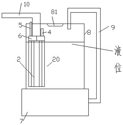
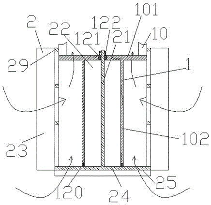
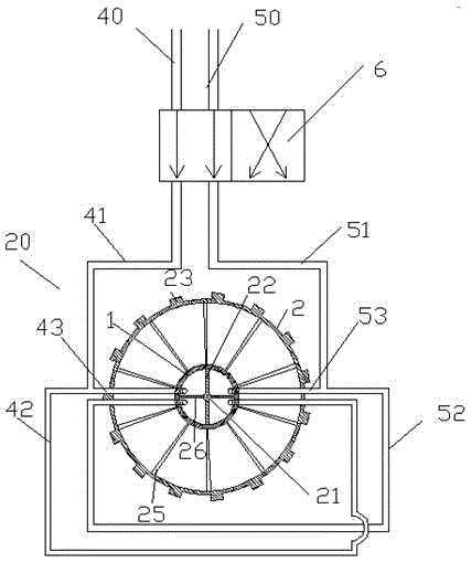
[0020] Attached below Figure 1-5 , the present invention will be described in detail.

[0021] A device with a central shaft with an electroplating coating and a buffer-type limit pipe section that uses air pressure to supply liquid, including a pressure air supply device 7, a pressure chamber 8, a pressure supply pipe 9, a liquid supply pipe 10 and The suction filter device 20, wherein the pressure air supply device 7 is used to provide pressure to the pressure chamber 8 through the pressure supply pipe 9, and the pressure chamber 8 can pressurize the liquid in the pressure chamber 8 and pass the liquid The pumping and filtering device 20 is arranged at the inner end of the liquid feeding pipe 10, and is used to filter the liquid when the liquid feeding pipe 10 draws liquid from the pressure chamber 8; the liquid feeding The outer end of the outlet pipe 10 is used to flow out the liquid; the top of the pressure chamber 8 is provided with a liquid inlet 81 .

[0022] The su...


PUM


Abstract

The invention provides a device provided with a buffered limiting pipeline section and a central shaft with an electroplating coat. The device supplies liquid through air pressure. The device comprises a compressed air supplying device (7), a pressure cavity (8), a pressure supplying pipe (9), a liquid supplying pipeline (10) and a drafting and filtering device (20). The compressed air supplying device (7) is used for providing pressure for the pressure cavity (8) through the pressure supplying pipe (9). The presser cavity (8) can pressurize liquid in the pressure cavity (8) and the liquid is delivered out through the liquid supplying pipeline (10). The drafting and filtering device (20) is arranged at the inner side end of the liquid supplying pipeline (10) and is used for filtering the liquid when the liquid supplying pipeline (10) drafts the liquid from the pressure cavity (8). The outer side end of the liquid supplying pipeline (10) is used for delivering out the liquid in a flowing mode. A liquid inlet (81) is formed in the top of the pressure cavity (8).

Description

technical field [0001] The invention relates to a device for supplying liquid by air pressure, and more particularly relates to a device for supplying liquid by air pressure which can automatically remove flocs. Background technique [0002] The device that uses air pressure to give liquid is a kind of equipment that sprays liquid widely used in agriculture, green land maintenance and industry. The water quality used by the device that uses air pressure to give liquid varies according to the water source. Therefore, in order to prevent the device that uses air pressure to give liquid from being affected by impurities in the liquid, the device that uses air pressure to give liquid The end of the draw line often has a filter structure. [0003] However, due to the suction formed by the device that uses the air pressure to give the liquid during operation, it is easy to absorb a large amount of impurities near the end of the liquid delivery pipeline; Over time, these floccule...

Claims


Application Information

Patent Timeline
Patent Type & Authority Patents(China)
IPC IPC(8): B05B9/04B05B15/02B08B7/02
CPCB05B9/04B05B12/008
Inventor 吴平芳
Owner 无锡丰荣电镀设备制造有限公司
Why Eureka
Try Eureka