Buffering spray gun assembly

An assembly and spray gun technology, applied in the direction of spray guns, explosion generating devices, abrasives, etc., can solve the problems of spray gun vibration, severe vibration, unevenness, etc., and achieve the effects of reducing mutual wear, reducing pulse frequency, and extending service life

Active Publication Date: 2014-06-18
WUXI WEIFU PRECISION MACHINERY MFG
View PDF11 Cites 3 Cited by
  • Summary
  • Abstract
  • Description
  • Claims
  • Application Information

AI Technical Summary

Problems solved by technology

[0003] In order to ensure that the shot peening effect reaches the standard, the flow rate of the steel shot during the shot peening process must be continuous, uniform and stable. However, when the spray gun on the existing shot peening equipment sprays the steel shot, the impact of the strong airflow causes the steel shot to vibrate violently in the spray gun , the steel shot flow is unstable and uneven, and it will make the spray gun vibrate, which is not easy to control, thus affecting the treatment effect

Method used


Image

  • Buffering spray gun assembly

Examples


Embodiment Construction

[0014] The present invention will be further described below with reference to the specific drawings and embodiments.

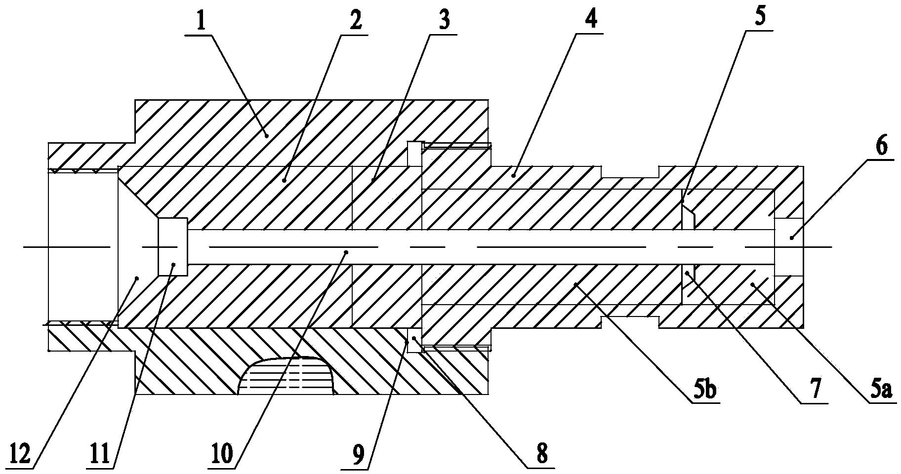
[0015] As shown in the figure: the buffer spray gun assembly in the embodiment is mainly composed of a spray head connecting sleeve 1, a spray sleeve 2, a buffer joint 3, a spray head locking sleeve 4, a nozzle 5 and an O-ring 8.

[0016] like figure 1 As shown, the nozzle sleeve 2 is arranged in the nozzle connecting sleeve 1, the rear end of the nozzle connecting sleeve 1 is provided with an interface for connecting the steel shot input pipeline, the front end of the nozzle connecting sleeve 1 is connected to the nozzle locking sleeve 4, and the nozzle 5 is placed in the nozzle. In the inner cavity of the locking sleeve 4, a buffer joint 3 is sandwiched between the rear end surface of the nozzle 5 and the front end surface of the spray sleeve 2, and the center of the spray sleeve 2, the buffer joint 3 and the nozzle 5 is provided with a central through hol...


PUM


Abstract

The invention relates to a buffering spray gun assembly. The buffering spray gun assembly comprises a spray head connection sleeve, a spray sleeve, a spray head locking sleeve, a buffering joint and a nozzle, wherein the spray sleeve is arranged in the spray head connection sleeve; an interface is formed in the rear end of the spray head connection sleeve and connected with a steel shot input pipeline; the spray head locking sleeve is connected to the front end of the spray head connection sleeve; the nozzle is arranged in an inner cavity of the spray head locking sleeve; a buffering joint is clamped between the back end face of the nozzle and the front end face of the spray sleeve; central through holes are formed in centers of the spray sleeve, the buffering joint and the nozzle; sizes of inner diameters of the central through holes are the same; the central through holes are coaxially communicated in a running-through manner to form a steel shot channel; the steel shot channel is communicated with a spray opening which is formed in the center of the front end of the spray head locking sleeve. The buffering spray gun assembly is reasonable in structure; since a buffering and damping structure is designed in the buffering spray gun assembly, the mutual abrasion loss can be effectively reduced, thereby prolonging the service lives of assembly parts in the spray gun assembly.

Description

technical field [0001] The invention relates to the improvement of a spray gun device of a shot blasting machine, in particular to a buffer spray gun assembly, which belongs to the technical field of shot peening intensive cleaning. Background technique [0002] Shot peening is a surface treatment process widely used at present. The high-speed shot flow produced by shot peening hits the surface of metal parts and effectively improves the microstructure. It produces high surface residual compressive stress on the surface of metal parts. The residual compressive stress can be Offset the tensile stress of the metal parts in the alternating force movement that causes the fatigue damage of the components, thereby greatly improving the fatigue life of the metal parts and improving the performance of various mechanical equipment. [0003] In order to ensure that the shot peening effect reaches the standard, the flow rate of the steel shot during the shot peening process must be con...

Claims


Application Information

Patent Timeline
Patent Type & Authority Applications(China)
IPC IPC(8): B24C5/02
Inventor 杜云丰朱璇如孙飞袁方殷存林
Owner WUXI WEIFU PRECISION MACHINERY MFG
Why Eureka
Try Eureka