
Tire burst monitoring sensor

A technology for monitoring sensors and tires, applied in the field of sensors, can solve the problems of driver inconvenience and pressure difference, and achieve the effect of good operation performance and safety performance

Active Publication Date: 2014-06-18
DONGGUAN NANNAR ELECTRONICS TECH
View PDF7 Cites 1 Cited by
  • Summary
  • Abstract
  • Description
  • Claims
  • Application Information

AI Technical Summary

Problems solved by technology

[0005] However, in the existing tire pressure monitoring and alarming devices of this type, when working, its reference cavity is completely isolated from the space on its outside, and the internal pressure remains constant. However, during the use of the car, the high-pressure gas of the tire must be released slowly. The ground leaks out, causing the monitoring cavity connected to the tire to slowly generate a pressure difference with the completely isolated reference cavity. When the pressure difference reaches a certain level, the elastic conductive sheet will bulge upward and deform, and the battery will The negative electrode of the tire is turned on, so that the alarm circuit board is energized to alarm and send out a signal. Therefore, when this type of tire pressure monitoring and alarm device is used to assist the process of the anti-flat tire device, it is impossible to distinguish between the slow air leakage of the tire and the rapid tire blowout. Air leakage, the normal slow air seepage is often misjudged as a car blowout and rapid air leakage, and triggers the explosion-proof device to start, causing the blow-out device to start even when the tire is not blown out, causing inconvenience to the driver

Method used


Image

  • Tire burst monitoring sensor
  • Tire burst monitoring sensor

Examples


Embodiment Construction

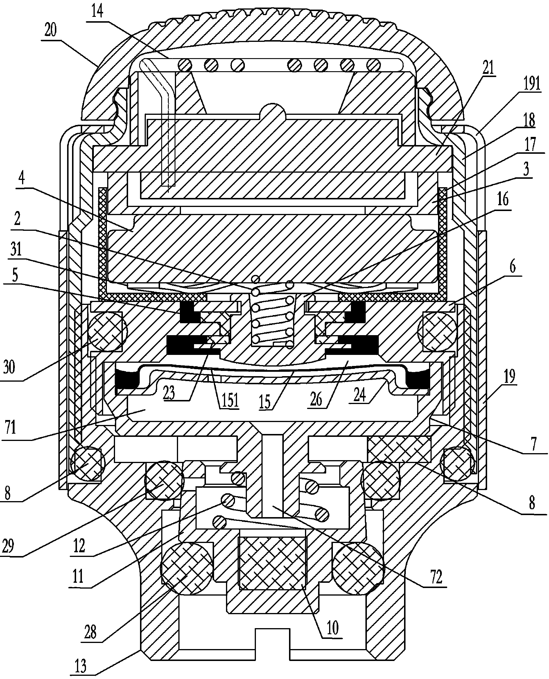
[0011] like figure 1 As shown, the tire puncture monitoring sensor includes a bottom nut 13 that can be screwed on the tire valve core (not shown in the figure) and a housing 18 screwed on the bottom nut 13. The bottom of the housing 18 passes through a sealing ring 8 is sealed with the bottom nut 13, there is a lens 20 on the top of the casing 18, the lens 20 seals the top of the casing 18 from the outside world, the inner space formed by the casing 18 and the bottom nut 13 is from top to bottom, and the alarm circuit board 21, the battery are installed 4. The elastic conductive sheet 15, the reference cavity assembly 7 and the top spring 12; the alarm circuit board 21 can be the transmitting module and the transmitting antenna 14 connected to it, and the positive lead-in end of the alarm circuit board 21 is directly or through the conductive member 3 and the battery below it The positive pole of 4 is turned on, and the negative pole of the alarm circuit board 21 is electrica...


PUM


Abstract

The invention discloses a tire burst monitoring sensor, wherein tiny exhaust damping holes are arranged on an elastic conducting plate; when a tire has normal and slow air permeation, although the air pressure of a monitoring cavity arranged above the elastic conducting plate is reduced, the air in a reference cavity can be discharged into the monitoring cavity through the exhaust damping holes on the elastic conducting plate, so that the air pressure in the reference cavity is guaranteed to be consistent with that in the monitoring cavity in time, a negative pole of a battery is not conducted by the upward bulge of the elastic conducting plate, and the long-time slow air permeation of the tire is avoided being identified as tire burst rapid air permeation by the tire burst monitoring sensor; during the tire burst rapid air permeation, the air pressure in the reference cavity can not be discharged outside in time, the air pressure difference between the reference cavity and the monitoring cavity rapidly rises, the elastic conducting plate is driven to protrude upwards, the negative pole of the battery is connected, a radio alarm signal and a flashing light alarm are transmitted by a transmission module, and a tire burst prevention device is started after a mainframe in an automobile receives the radio alarm signal, so that the automobile is guaranteed not to turn on the side.

Description

technical field [0001] The invention relates to a sensor which can monitor in real time whether rapid air leakage occurs in automobile tires. Background technique [0002] It is unpredictable for the car to be scratched or punctured when the car is running on a complex road. Therefore, in order to prevent the car from rolling over due to a flat tire, the prior art installs a flat tire device on the car. When started in time, the car with a flat tire can keep the balance of the body, thereby ensuring driving safety. Whether the run-flat device can be started in time requires the assistance of a sensor that can monitor whether the car tires have rapid air leakage in real time, so as to transmit the monitored rapid air leakage signal and trigger explosion-proof when the car has a rapid tire leak. The tire unit starts. [0003] In the prior art, there are a variety of sensors that can monitor whether there is air leakage in automobile tires in real time. For example, the tire...

Claims


Application Information

Patent Timeline
Patent Type & Authority Applications(China)
IPC IPC(8): B60C23/04
Inventor 朱晓东陈齐何万顺
Owner DONGGUAN NANNAR ELECTRONICS TECH
Learn More