Rack end protection method of electric power steering system

An electric power steering and end protection technology, applied in electric steering mechanism, automatic steering control components, steering mechanism, etc., can solve problems such as reduced protection effect, increased cost, noise and discomfort for drivers and passengers

Inactive Publication Date: 2014-06-18
LIANCHUANG AUTOMOBILE ELECTRONICS
View PDF7 Cites 33 Cited by
  • Summary
  • Abstract
  • Description
  • Claims
  • Application Information

AI Technical Summary

Problems solved by technology

This may cause damage to the mechanical structure, and the resulting noise may also cause discomfort to the occupants
[0021] The existing rack end protection strategy only considers the first working condition, that is, when the steering wheel 11 is held for a long time, a certain limit is placed on the assist torque to reduce the motor curren

Method used


Image

  • Rack end protection method of electric power steering system
  • Rack end protection method of electric power steering system
  • Rack end protection method of electric power steering system

Examples


Embodiment Construction

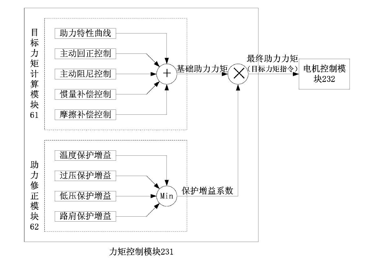
[0040] see Figure 4 , which is the torque control module of the electric power steering system of the present application. and image 3 Compared with the existing torque control module shown, the present application adds a rack end protection gain module in the power assist correction module 62 .

[0041] see Figure 5 , the rack end protection method of the electric power steering system of the present application is: when the rack of the steering gear 13 moves toward the rack end and enters the rack end protection area, the rack end protection gain module uses the steering wheel The rotation angle, rotation angular velocity and rotation torque of 11 are used as input, and the gain value of rack end protection is output after calculation. After the rack end protection gain value is multiplied by the base assist torque calculated by the target torque calculation module 61 , it is output to the motor control module 232 as a final target torque command.

[0042] Figure 4 ...


PUM


Abstract

The application discloses a rack end protection method of an electric power steering system. When a rack of a steering gear moves towards the end of the rack and enters a rack end protection area, an ECU (electronic control unit) of the electric power steering system takes a rotating angle of a steering wheel, the speed of the rotating angle and rotating torque as input to calculate a rack end protection gain value which serves as a multiplier during assisting torque calculation. The rack end protection gain value is the product of a basic gain coefficient, a rotating speed gain coefficient and a rotating torque gain coefficient. The basic gain coefficient decreases progressively as the absolute value of the rotating angle of the steering wheel increases. The rotating speed gain coefficient decreases progressively as the absolute value of the rotating angle of the steering wheel increases. The rotating torque gain coefficient increases progressively as the absolute value of the rotating angle of the steering wheel increases. According to the rack end protection method of the electric power steering system, during working conditions of rack ends, current output can be limited, temperature rise can be reduced and mechanical impact of the rack ends can be avoided.

Description

technical field [0001] The present application relates to an electric power steering system (Electric Power Steering, EPS system for short) of an automobile. Background technique [0002] see figure 1 , which is the mechanical steering system on the car. It includes a steering wheel 11 , a steering column 12 , a steering gear 13 , a steering tie rod 14 and steering wheels 15 . When the driver applies a steering force to act on the steering wheel 11, the steering shaft mechanism built in the steering column 12 is driven to rotate. Engagement, thereby drives rack structure to do translation in steering gear 13, because rack mechanism is hard-connected with steering rod 14, thereby by steering rod 14 exerts pulling force or thrust on steering wheel 15, completes automobile steering action. [0003] see figure 2 , which is the electric power steering system on the car. On the basis of the mechanical steering system, it adds: [0004] ——The torque angle sensor 21 is used t...

Claims


Application Information

Patent Timeline
IPC IPC(8): B62D5/04B62D3/12B62D6/00B62D113/00B62D117/00B62D119/00
Inventor 郑鸿云李若飞金灿龙吕帅罗来军
Owner LIANCHUANG AUTOMOBILE ELECTRONICS
Why Eureka
Try Eureka