Bilateral locking device

A locking device and locking lever technology, applied in the field of locks, can solve the problems of affecting the normal use of the locking device, insufficient to effectively overcome the spring force, low assembly work efficiency, etc., so as to avoid the unqualified operating force and the incomplete handle. The effect of resetting and improving the efficiency of assembly work

Inactive Publication Date: 2014-06-18
上海琦天汽车科技有限公司
View PDF7 Cites 23 Cited by
  • Summary
  • Abstract
  • Description
  • Claims
  • Application Information

AI Technical Summary

Problems solved by technology

[0004] 1) After the sliding shaft is connected to the cam part, it is not easy to disassemble, and it is easy to damage the related parts when the damaged parts are removed during the maintenance of the device, which is very inconvenient for maintenance;
[0005] 2) Although the left and right cam parts are similar in shape, they are not interchangeable, and it is difficult to identify the left and right during assembly, which is prone to assembly errors and affects the efficiency of assembly operations;
[0006] 3) The spring needs to be assembled into the inner hole of the cam part in advance, and then installed into the cylindrical part of the handle by inserting and rotating. The assembly operation is complicated, the working time is long, and the assembly operation efficiency is low;
[0007] 4) In order to close the impact sound, an O-ring is set, and the friction between the outer periphery of the O-ring and the inner surface of the cylindrical part of the handle is used to slow down the reset movement speed of the spring to the cam part, but the dimensional accuracy of the O-ring It is difficult to control. If the size of the O-ring is too large, the friction force will be too large, which will affect the operating force of the handle or cause the sliding shaft to not be fully reset, thus affecting the normal use of the locking device. If the size of the O-ring is too small, the friction force will be reduced. Not enough to effectively overcome the elastic force of the spring, and the impact sound will still occur;
[0008] 5) The inner hole of the cylindrical part of the handle is realized by the mold structure of the slider core pulling. The handle made of this mold structure will form a sharp corner on the edge, which will easily cause scratches on the hand when operating the handle, and the assembly safety is low.

Method used


Image

  • Bilateral locking device
  • Bilateral locking device
  • Bilateral locking device

Examples


Embodiment Construction

[0055] The embodiments of the present invention will be described in further detail below in conjunction with the accompanying drawings, but the present embodiments are not intended to limit the present invention, and any similar structures and similar changes of the present invention should be included in the protection scope of the present invention.

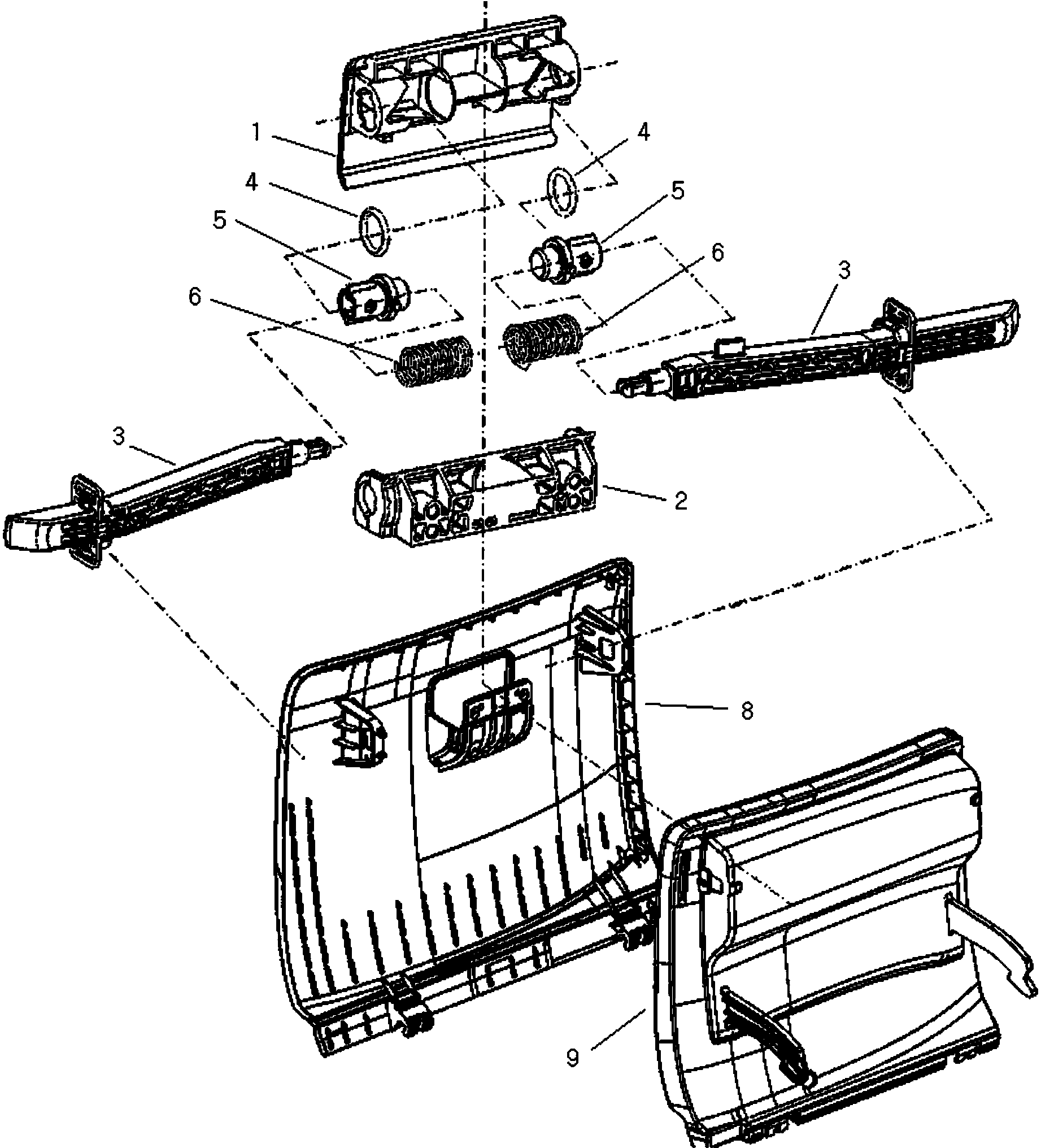
[0056] Such as Figure 1-21 As shown, a double-sided locking device provided by the embodiment of the present invention includes an outer cover plate 8, a main body part 2, and a handle 1;

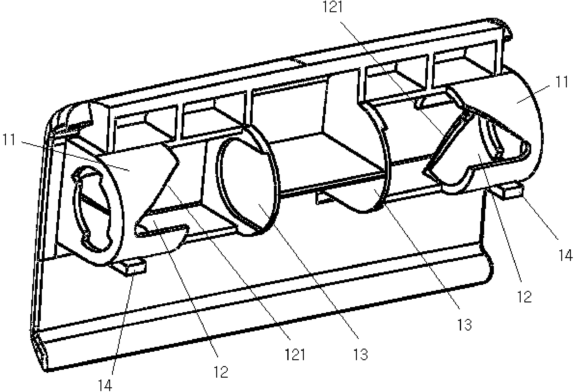
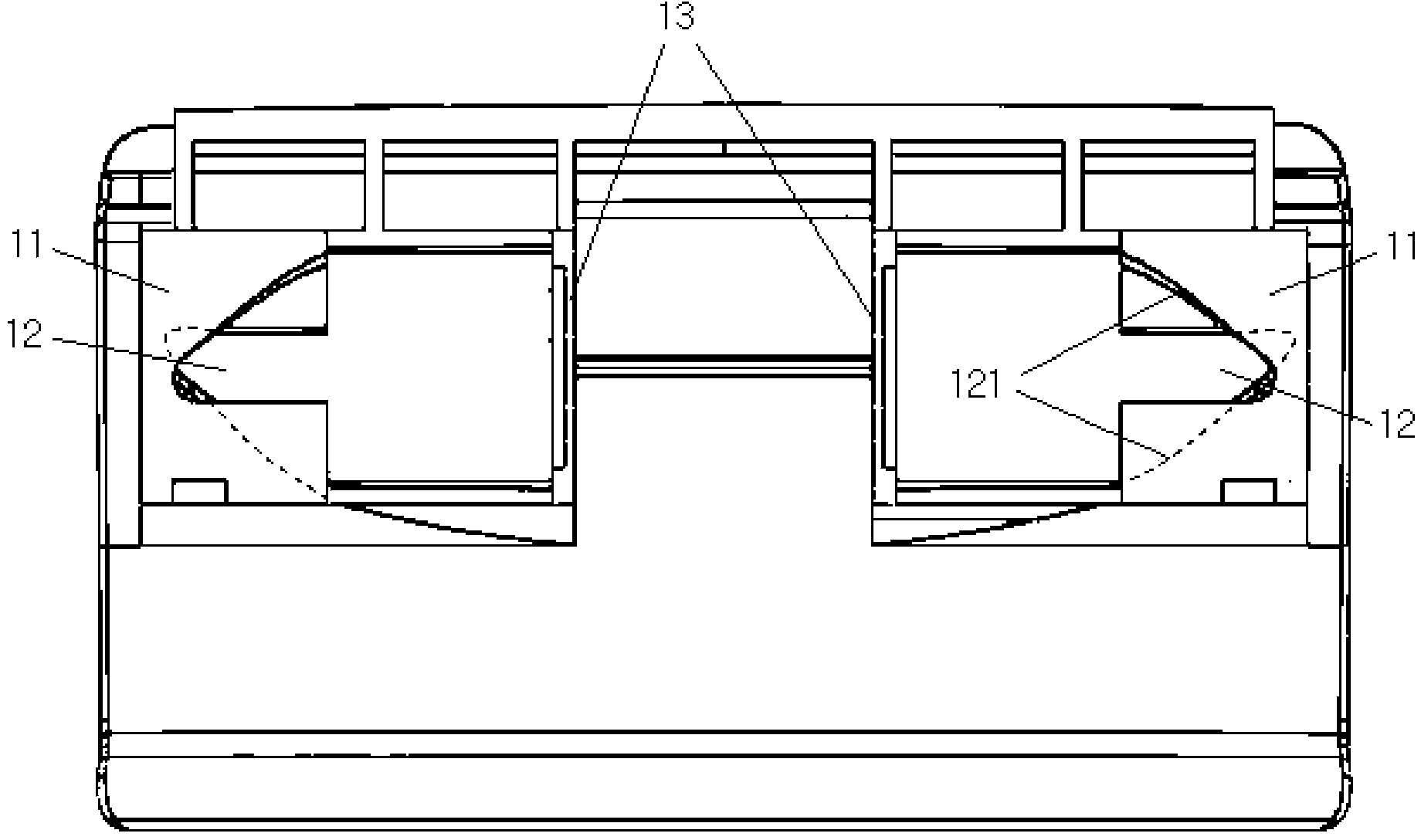
[0057] The back side of the outer cover plate 8 is fixed with an annular lock bar buckle 81 on the left and right (see Figure 16 );

[0058] The main body part 2 is fixed on the outer cover plate 8 and is located between two lock bar buckles, and the main body part is provided with a main body end hole 21 on the left and right (see Figure 9 , Figure 10 ), each body end hole 21 has two axisymmetrically distributed end hole bayonet soc...


PUM


Abstract

The invention relates to a bilateral locking device, relates to the technical field of locksets and aims to solve to the technical problems of inconvenient maintenance and low assembling efficiency of an existing device. The device comprises an outer cover plate, a main-body part and a handle, wherein the main-body part is fixedly arranged on the outer cover plate, and the handle is pivoted with the main-body part; a left sliding-shaft barrel and a right sliding-shaft barrel are respectively and fixedly arranged at the back of the handle, a sliding shaft is arranged in each sliding-shaft barrel, and the two sliding shafts are respectively driven to extend and retract through the matching of the shaft-barrel guiding ports and the sliding-shaft pins of the two sliding-shaft barrels and the sliding shafts in the barrels; a shaft hole is formed in the clamping end of each sliding shaft, two disassembling holes are formed in the hole wall of each shaft hole, and a stop block is fixedly arranged in each shaft hole; the left side and the right side of the main-body part are respectively provided with a locking rod, the hook end of each locking rod is inserted into the shaft hole of the corresponding sliding shaft, and the stop block in each shaft hole is hooked after two elastic clamping hooks at the hook end of the corresponding locking rod penetrate through a clamping hole in the corresponding shaft hole. The device provided by the invention is suitable for being used as the box cover of an automobile glove box.

Description

technical field [0001] The invention relates to lock technology, in particular to a technology of a double-sided locking device. Background technique [0002] The Chinese patent application No. 200310103473.6 discloses a locking device that can be used in a glove box that is axially supported and rotatable on the dashboard of a vehicle. The device is equipped with a pair of A cam part, a pair of compression springs, a pair of O-rings, a cam groove is formed on the outer circumference of the cam part; when the operating handle is turned, the protruding part formed on the inner surface of the cylindrical part of the handle moves along the groove edge of the cam groove , the cam part retracts inward in the cylindrical part; when the operating handle is released, the cam part protrudes outward under the action of the compression spring, and the O-ring decelerates the cam part by the friction force of the circumference to prevent a large Impact sound; connect the cam part with t...

Claims


Application Information

Patent Timeline
Patent Type & Authority Applications(China)
IPC IPC(8): E05B83/30E05B63/14E05B85/00E05B77/38E05B85/10
Inventor 苏新文
Owner 上海琦天汽车科技有限公司
Why Eureka
Try Eureka