Power generating device

A technology for generating devices and power, which is applied in the field of power generating devices and can solve problems such as weak adaptability

Inactive Publication Date: 2014-06-18
邱金和
View PDF0 Cites 0 Cited by
  • Summary
  • Abstract
  • Description
  • Claims
  • Application Information

AI Technical Summary

Problems solved by technology

[0005] The main purpose of the present invention is to provide a power generating device with simple structure, convenient operation a

Method used


Image

  • Power generating device
  • Power generating device
  • Power generating device

Examples


Embodiment Construction

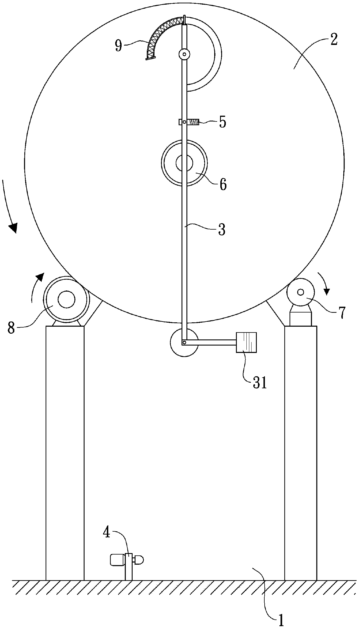
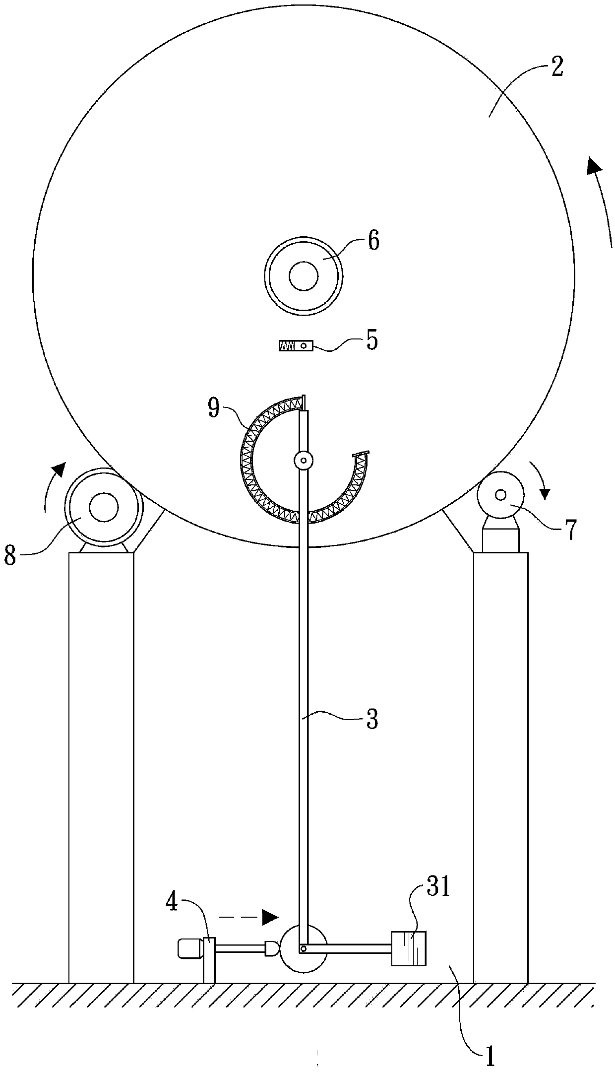
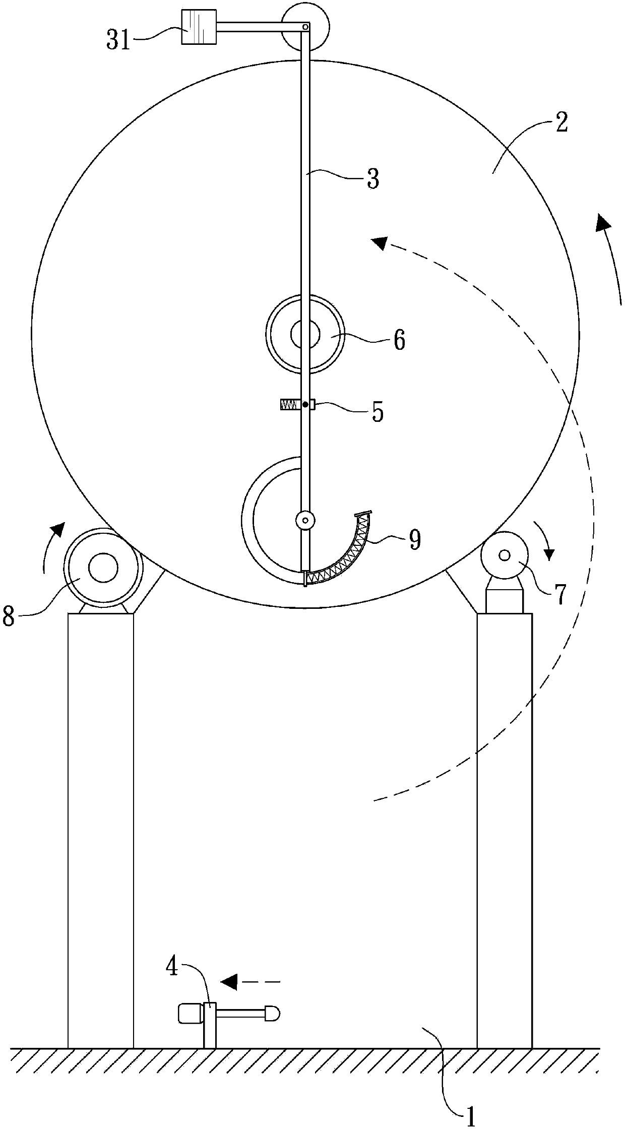
[0021] see Figure 1~3 , the content of the drawing is a preferred embodiment of the power generation device 1 of the present invention, which is composed of a base body 1, a turntable 2, an L-shaped rod body 3, a striker 4 and a tenon 5.

[0022] The turntable 2 is pivotally connected to the base body 1, so that the turntable 2 can rotate relative to the base body 1, and the center of the turntable 2 is connected with an energy collecting device 6, the turntable 2 can be driven by a motor 7 to run, and can be driven by a stable Speed ​​device 8 and stable operation. Wherein, the motor 7 is powered by an energy mechanism with low output power or unstable output power.

[0023] One end of the L-shaped rod body 3 is pivotally arranged on the turntable 2, and the other end extends beyond the outer circumference of the turntable 2, and is provided with a weight 31, and the front end of the L-shaped rod body 3 (that is, away from the end that is provided with the weight block 31) ...


PUM


Abstract

The invention discloses a power generating device. The power generating device comprises a base body, a turntable, an L-shaped rod body, a striker and a buckling tenon, wherein the turntable is connected to the base body in a pivoting way; an energy-collecting device is connected to the center; one end of the L-shaped rod body is arranged on the turntable in the pivoting way and the other end extends to be beyond the periphery of the turntable; an elastomer is connected between the front end of the L-shaped rod body and the turntable; when the turntable rotates, the elastomer is in an extending state due to the rotation of the turntable; the striker is arranged at the place, close to the downside of the turntable, on the base body and is used for striking the L-shaped rod body which is rotated to the place below the turntable, so that the L-shaped rod body swings, the elastomer elastically reciprocates to drive the turntable to rotate, and the energy-collecting device is driven to rotate to accumulate energy; the buckling tenon is correspondingly arranged on one side, with the L-shaped rod body, of the turntable and is used for releasing or buckling the L-shaped rod body.

Description

technical field [0001] The invention relates to a power generating device with simple structure, convenient operation and low cost. Background technique [0002] In recent years, as the earth's energy is about to face the crisis of energy depletion, countries around the world are constantly actively developing and utilizing "wind power", "solar power", "hydraulic power", "waves", "tide" or "geothermal power" to generate electricity energy, in order to slow down the speed at which traditional energy is consumed. [0003] However, whether the above-mentioned methods of using "wind", "solar", "hydraulic", "wave", "tide" or "geothermal" to generate energy are all subject to "regional" restrictions; for example, some The wind power is not strong all year round in the area, that is, "wind power" cannot be used to generate energy; similarly, the climate in some areas is rainy all the year round, so "solar energy" cannot be used naturally; and "hydraulic power" and "geothermal powe...

Claims


Application Information

Patent Timeline
IPC IPC(8): F03G3/00
CPCF03G7/10
Inventor 邱金和
Owner 邱金和
Why Eureka
Try Eureka