Motorized spindle rigidity test device

A technology for testing devices and electric spindles, which is applied in the direction of measuring devices, testing of mechanical components, testing of machine/structural components, etc., can solve problems such as the inability to simulate the influence of electric spindles, and achieve easy assembly and maintenance, and a simple and compact device structure Effect

Inactive Publication Date: 2014-06-18
CHONGQING UNIV
View PDF7 Cites 7 Cited by
  • Summary
  • Abstract
  • Description
  • Claims
  • Application Information

AI Technical Summary

Problems solved by technology

Under real working conditions, the dynamic cutting force on the tool acts indirectly on the electric spindle, and the cutting force still has a certain frequency. At the same time, the spindle is also subjected to torque, which has a great impact on the performance and reliability of the high-speed electric spindle under test. None of the existing loading devices can simulate the influence of dynamic high-frequency cutting force on the electric spindle

Method used


Image

  • Motorized spindle rigidity test device
  • Motorized spindle rigidity test device
  • Motorized spindle rigidity test device

Examples


Embodiment Construction

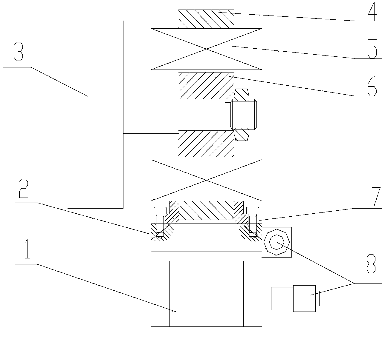
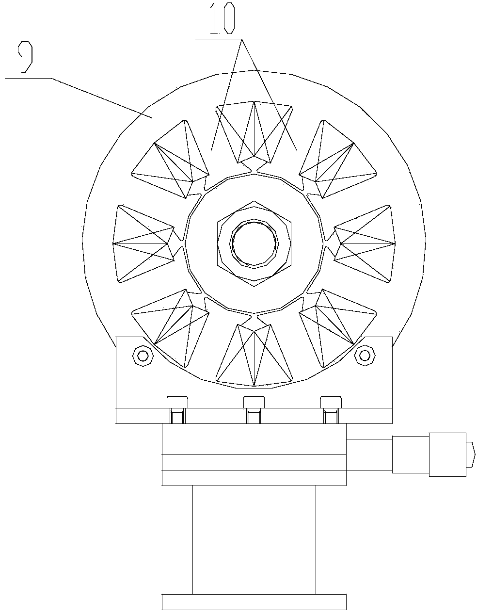
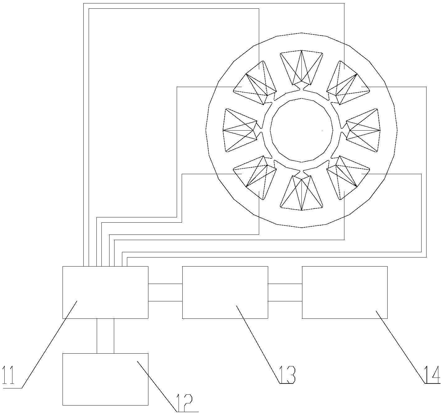
[0018] figure 1 It is a structural schematic diagram of the present invention, figure 2 for figure 1 right view of the image 3 It is a schematic diagram of the structure of the circuit control module. As shown in the figure, the electric spindle 3 stiffness testing device in this embodiment includes an electromagnetic loading device and a circuit control module. The electromagnetic loading device includes a magnetically conductive ring 6 coaxially fixedly connected with the electric spindle 3 and a magnetically conductive ring 6 sleeved on the magnetically conductive ring. 6 Outside the excitation device, the circuit control module is used to control the circuit in the excitation device.

[0019] In this embodiment, the excitation device includes an iron core 4 and a coil 5 wound around the iron core for providing magnetic flux to it along the radial direction of the magnetic conduction ring 6, and the iron core 4 includes an outer ring coaxially arranged with the magneti...


PUM


Abstract

The invention discloses a motorized spindle rigidity test device which comprises an electromagnetism loading device and a circuit control module, wherein the electromagnetism loading device comprises a magnetic conductance ring which is coaxially and fixedly connected with a motorized spindle and an excitation device which is sleeved outside the magnetic conductance ring; the circuit control module is used for controlling a circuit in the excitation device. According to the motorized spindle rigidity test device, the dynamic loading to the high-speed motorized spindle is realized; relative o a static test and a no-load test, the actual working state of the motorized spindle is more accurately simulated by the motorized spindle rigidity test device, a constructive opinion is proposed for the design and the optimization of the motorized spindle, parts of the device are easy to design and manufacture in a serialization and standardization way, the structure of the device is simple and compact, and the maintenance and the assembly are easy.

Description

technical field [0001] The invention relates to a test device, in particular to a test device for the stiffness of an electric spindle. Background technique [0002] As the core component of high-speed machining machine tools, high-speed electric spindles have always been the focus of designers' attention on their dynamic performance, which directly affects the machining accuracy and production efficiency of machine tools. However, due to the structural characteristics of the high-speed electric spindle, it has always been difficult to test it online. At present, the research on the dynamic performance of the electric spindle is mainly based on simulation and finite element analysis, and the dynamic test methods are mostly concentrated on the no-load operation test. In engineering, the hammering method, the torque tachometer method, the use of cutting force as the load and the use of transmission mode to decelerate the load are used. However, these loading methods are all c...

Claims


Application Information

Patent Timeline
Patent Type & Authority Applications(China)
IPC IPC(8): G01M13/00
Inventor 合烨李培明卢艳陈小安
Owner CHONGQING UNIV
Why Eureka
Try Eureka