Passenger car body-in-white bending and torsion stiffness test restraint device

A restraint device and body-in-white technology, which is applied in the field of vehicle inspection, can solve the problems of body deformation, different sizes, and large body stiffness values, etc., and achieve the effect of easy adjustment

Active Publication Date: 2014-06-18
GUANGZHOU AUTOMOBILE GROUP CO LTD
View PDF7 Cites 22 Cited by
  • Summary
  • Abstract
  • Description
  • Claims
  • Application Information

AI Technical Summary

Problems solved by technology

[0018] a) It does not meet the constraint requirements of the degree of freedom of the space mechanism, and introduces constraints beyond the six degrees of freedom of the body, which will generate preload when the body is installed and fixed; each stage of body development needs to test the stiffness value, and the over-c

Method used


Image

  • Passenger car body-in-white bending and torsion stiffness test restraint device
  • Passenger car body-in-white bending and torsion stiffness test restraint device
  • Passenger car body-in-white bending and torsion stiffness test restraint device

Examples


Embodiment 1

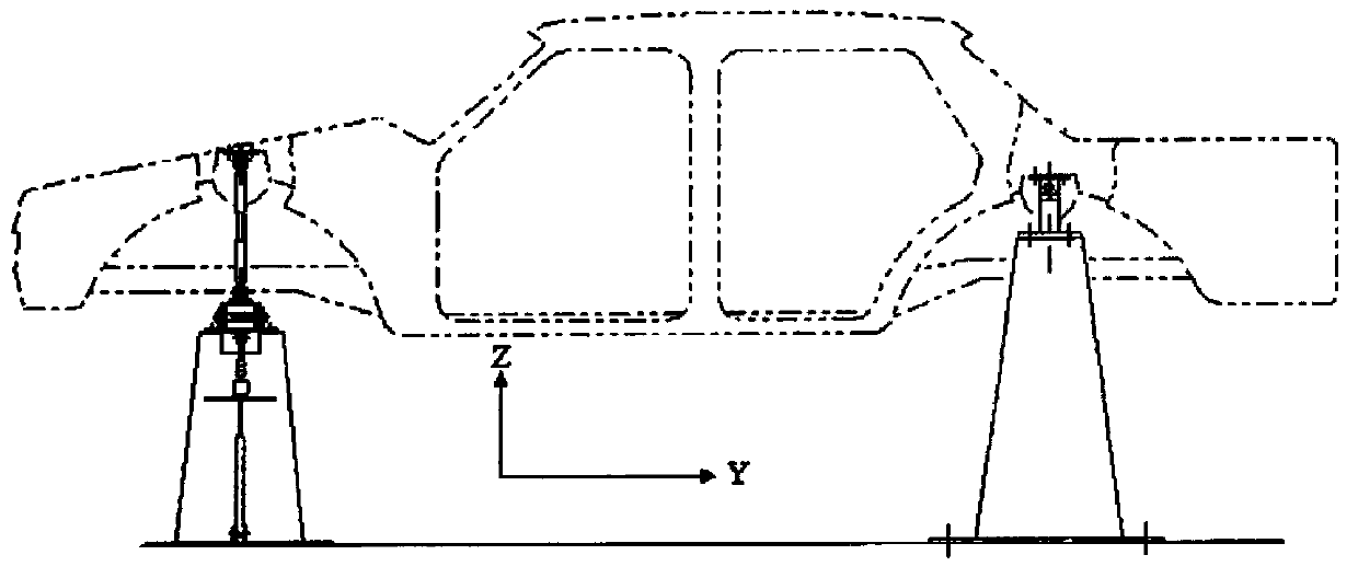
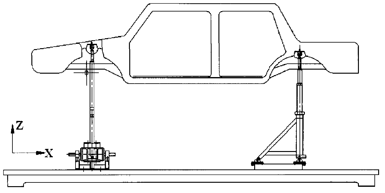
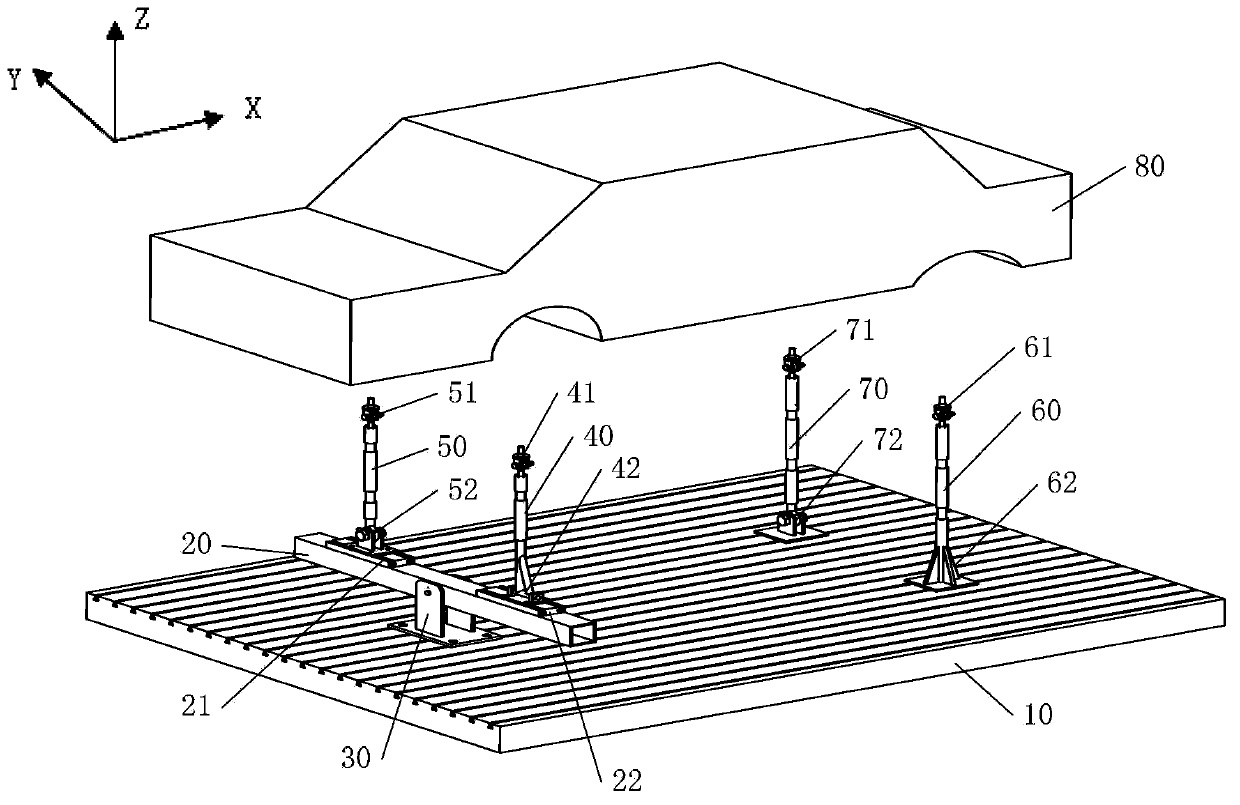
[0053] Such as image 3 , Figure 4 , Figure 5 , Image 6 with Figure 7 As shown, the restraint device for the bending and torsional rigidity test of the passenger car body-in-white in this embodiment includes: a workbench 10, a torsion beam 20, a first column 40 (ie, the left front column), a second column 50 (ie, the right front column), a Three columns 60 (i.e. the left rear column) and the fourth column 70 (i.e. the right rear column), wherein the torsion beam 20 is laterally arranged on one side of the workbench 10 through the support 30, and can be laterally twisted around the support 30; the first column 40 and the lower ends of the second column 50 are arranged on both sides of the torsion beam 20 respectively;

[0054] In this embodiment, the top ends of the first column 40, the second column 50, the third column 60 and the fourth column 70 are respectively provided with connecting pieces 41, 51 which limit the three degrees of freedom of movement but not the th...

Embodiment 2

[0064] Such as Figure 9 As shown, in the second embodiment, the lower ends of the first column 40 and the second column 50 are connected to the torsion beam 20 using a connecting piece that restricts three degrees of freedom of movement but not three degrees of freedom of rotation (for example, using a ball joint) , the lower end of the fourth column 70 is connected to the workbench 10 by a one-way rotating hinge, and the lower end of the third column 60 is fixed on the workbench 10 . The rest of the structure is the same as that of Embodiment 1, and will not be described again here.

[0065] Utilizing the structure of the second embodiment, the six spatial degrees of freedom of the vehicle body are just completely constrained, that is, the degree of freedom of the vehicle body is 0, and the purpose of the present invention can also be achieved.

Embodiment 3

[0067] Such as Figure 10 As shown, in the third embodiment, the lower end of the second column 50 is connected to the twisted beam 20 using a one-way rotating rotary hinge, and the lower end of the first column 40 is connected to the twisted beam 20, and the lower end of the fourth column 70 is connected to the workbench. 10 is connected by a connecting piece (for example, using a ball joint) that restricts three degrees of freedom of movement but not three degrees of freedom of rotation, and the lower end of the third column 60 is fixed on the workbench 10 . The rest of the structure is the same as that of Embodiment 1, and will not be described again here.

[0068] Utilizing the structure of the third embodiment, the six spatial degrees of freedom of the vehicle body are just completely constrained, that is, the degree of freedom of the vehicle body is 0, and the purpose of the present invention can also be achieved.


PUM


Abstract

The invention provides a passenger car body-in-white bending and torsion stiffness test restraint device which includes a workbench, a torsion crossbeam, a first column, a second column, a third column, and a fourth column. The torsion crossbeam is horizontally arranged on one side of the workbench via a support, and can rotate horizontally around the support. The lower end of the first column and the lower end of the second column are arranged on the two sides of the torsion crossbeam respectively. The lower end of the third column and the lower end of the fourth column are arranged on the other side of the workbench at an interval. The top end of each column is provided with a connecting member which limits three mobile degrees of freedom but does not limit three rotational degrees of freedom. The lower end of the third column or the lower end of the fourth column is fixed on the workbench, and among the connecting members between the lower ends of the remaining three columns and the workbench or the torsion crossbeam, one is a unidirectional rotary hinge, and the other two are connecting members which limit three mobile degrees of freedom but does not limit three rotational degrees of freedom. In such a manner, the six degrees of freedom of the car body space are restrained, the influence of a frame to the car body stiffness is eliminated, and the car body posture can be easily adjusted.

Description

technical field [0001] The invention relates to the technical field of vehicle detection, in particular to a restraint device for a bending and torsional rigidity test of a body-in-white of a passenger car. Background technique [0002] Body in White refers to the body before welding but not painted, excluding moving parts such as doors and hoods. Body-in-white plus interior and exterior decoration (including instrument panel, steering column, seat, front and rear windshield, rearview mirror, fender, water tank, headlight, carpet, interior guard, etc.) and door, hood , trunk lid and electronic and electrical systems constitute the body in the true sense, which is called trimmed body in the industry, that is, the assembled body, and on this basis, the chassis (including engine, gearbox, transmission system, braking system, Suspension system, exhaust system, etc.) make up the whole vehicle. [0003] Bending stiffness and torsional stiffness are one of the important propertie...

Claims


Application Information

Patent Timeline
IPC IPC(8): G01M17/007
Inventor 李涛田川超卢海波董川川谭能堃
Owner GUANGZHOU AUTOMOBILE GROUP CO LTD
Why Eureka
Try Eureka