
LED support and LED luminous body

A technology of LED brackets and illuminants, which is applied in semiconductor devices, electrical components, circuits, etc., can solve problems that affect LED reliability, hidden dangers of deformation, and increase costs, so as to ensure normal light output, strengthen bonding force, and improve production efficiency. Effect

Active Publication Date: 2014-06-18
SHENZHEN REFOND OPTOELECTRONICS
View PDF6 Cites 6 Cited by
  • Summary
  • Abstract
  • Description
  • Claims
  • Application Information

AI Technical Summary

Problems solved by technology

The existing dam manufacturing method is to make dams on the substrate before packaging, and then install the chips one by one in the middle of the dams. This method has complicated procedures, low efficiency, and increases costs. On the substrate, there is a hidden danger of deformation after long-term use, which affects the reliability of the LED

Method used


Image

  • LED support and LED luminous body
  • LED support and LED luminous body
  • LED support and LED luminous body

Examples


Embodiment Construction

[0010] In order to make the object, technical solution and advantages of the present invention clearer, the present invention will be further described in detail below in conjunction with the accompanying drawings and embodiments. It should be understood that the specific embodiments described here are only used to explain the present invention, not to limit the present invention.

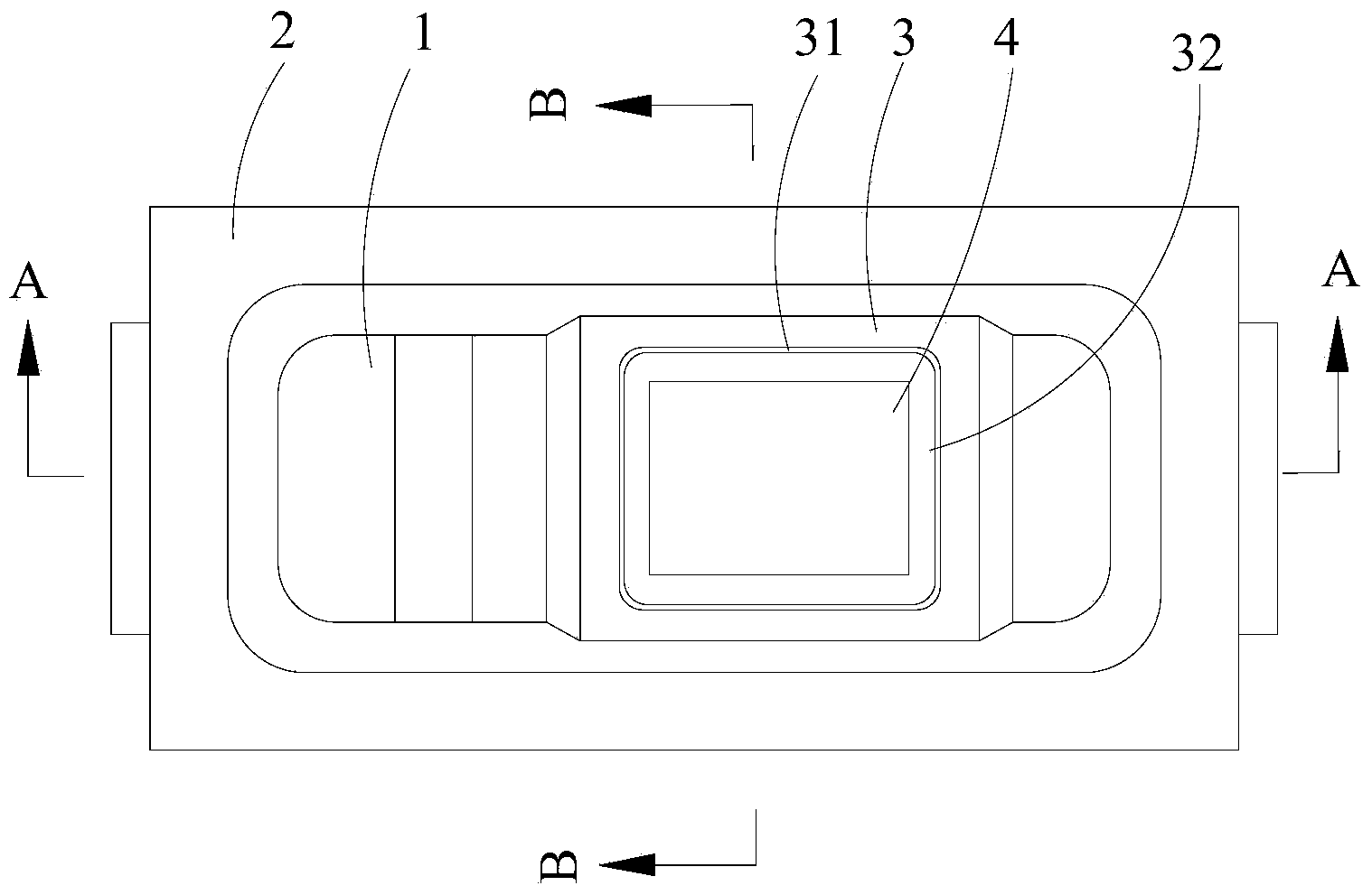
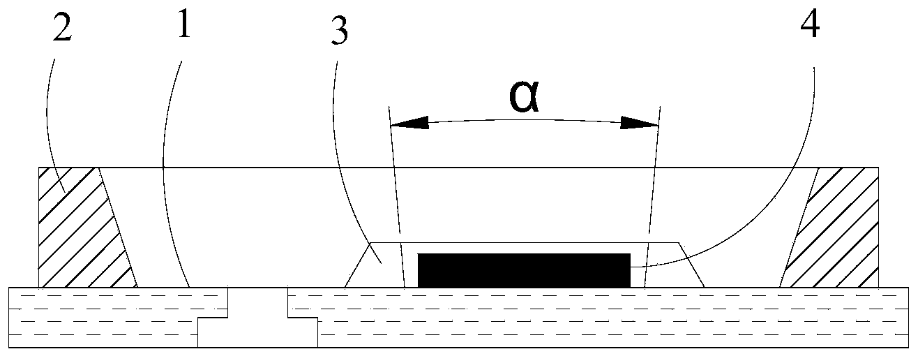
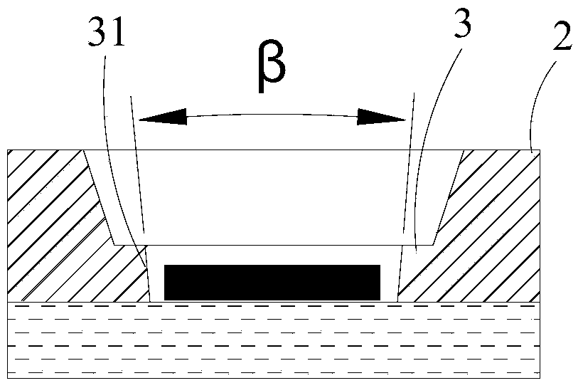
[0011] see figure 1 The LED bracket provided by the embodiment of the present invention includes a metal substrate 1 and a plastic reflective cup 2 arranged on the metal substrate 1, and a dam 3 protruding from the metal substrate 1 is provided in the area enclosed by the plastic reflective cup 2 , The dam 3 is integrally formed with the plastic reflection cup 2, and the materials are the same. The size of the dam 3 is slightly larger than that of the LED chip 4 and is used for installing the LED chip 4 . see further figure 2 , 3 The depth of the dam 3 is 1 / 3 to 3 times, more preferably 1 to 2...


PUM


Abstract

The invention is applicable to the field of illumination technologies and provides an LED support. The LED support comprises a metal substrate and a plastic reflection cup arranged on the metal substrate. A protruding box dam for installation of an LED chip is arranged in a region defined by the plastic reflection cup. The box dam and the plastic reflection cup are integrally formed. The depth of the box dam is one-third to three times the thickness of the LED chip. The opening angle of each set of opposite inner side faces of the box dam is smaller than 120 degrees. Because the plastic reflection cup and the box dam are integrally formed on the metal substrate, the procedures are reduced, the production efficiency is improved, the LED support is not prone to deformation and stripping, the binding force between the plastic reflection cup and the metal substrate is enhanced, and the reliability of the LED chip is improved; the depth of the box dam is designed to be one-third to three times the thickness of the LED chip, and the opening angle of each set of opposite inner side faces of the box dam is limited below 120 degrees, so the side faces are prevented from absorbing light, the normal light emergence of the obverse sides is guaranteed, and the luminous efficiency is improved.

Description

technical field [0001] The invention relates to the technical field of LED lighting, in particular to an LED bracket and an LED illuminant. Background technique [0002] LED is one of the most widely used light sources at present. During the manufacturing process of LED, dams are usually made around the chip to facilitate the coating of fluorescent glue or packaging glue, or to prevent the sidewall of the chip from absorbing light. The existing dam manufacturing method is to make dams on the substrate before packaging, and then install the chips one by one in the middle of the dams. This method has complicated procedures, low efficiency, and increases costs. On the substrate, there is a hidden danger of deformation after long-term use, which affects the reliability of the LED. Contents of the invention [0003] The object of the present invention is to provide a novel LED bracket, aiming at simplifying the process, improving production efficiency and improving its reliabi...

Claims


Application Information

Patent Timeline
Patent Type & Authority Applications(China)
IPC IPC(8): H01L33/48H01L33/60
CPCH01L33/56H01L33/60
Inventor 游志
Owner SHENZHEN REFOND OPTOELECTRONICS
Learn More