Rotor assembly and permanent magnet motor comprising same

A technology of permanent magnets and components, applied in electric components, magnetic circuit rotating parts, magnetic circuits, etc., can solve problems such as increasing the material cost of permanent magnet motors

Active Publication Date: 2014-06-18
EMERSON CLIMATE TECH (SUZHOU) CO LTD
View PDF8 Cites 32 Cited by
  • Summary
  • Abstract
  • Description
  • Claims
  • Application Information

AI Technical Summary

Problems solved by technology

The downside in this case is the use of high-grade permanent magnets in locations where greater resistance to demagnetization is not required, increasing the material cost of permanent magnet motors

Method used


Image

  • Rotor assembly and permanent magnet motor comprising same
  • Rotor assembly and permanent magnet motor comprising same
  • Rotor assembly and permanent magnet motor comprising same

Examples


Embodiment Construction

[0015] Exemplary embodiments according to the present invention will be described in detail below with reference to the accompanying drawings. The description of the exemplary embodiments is for the purpose of illustration only, and in no way limits the invention and its application or usage.

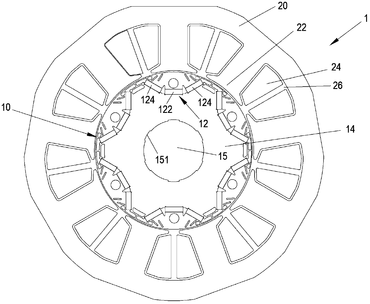
[0016] With reference to the accompanying drawings, figure 1 A schematic plan view of an embodiment of a permanent magnet motor 1 according to the invention is shown. The permanent magnet motor 1 according to the present invention includes a stator assembly 20 and a rotor assembly 10 rotatably accommodated in an inner cavity of the stator assembly 20 . According to the prior art of constructing rotating electrical machines, by using the rotor shaft, rotor bearings and end shields ( figure 1 not shown in ) to position the rotor assembly 10 within the lumen of the stator assembly 20 .

[0017] The stator assembly 20 defines a plurality of stator teeth 22 extending in a radial direction...


PUM


Abstract

The invention discloses a rotor assembly for a permanent magnet motor. The rotor assembly comprises a rotor iron core and multiple permanent magnet groups uniformly distributed along the peripheral direction of the rotor iron core; each of the permanent magnet group comprises a first permanent magnet positioned in the middle of the permanent magnet group and second permanent magnets positioned at the end parts of the permanent magnet group, wherein first magnet isolating slots are arranged between the end part edges, away from the first permanent magnet, of the second permanent magnets, and the outer periphery of the rotor iron core; the first magnet isolating slots extend along the outer periphery of the rotor iron core in the extension direction of the permanent magnets. According to the rotor assembly, magnetic fields between stator teeth and the rotor permanent magnets are optimized by the magnet isolating slots, and the reversing of the hysteresis magnetic field is effectively inhibited, so the magnetic field change is reduced and the pulse of the output torque of a motor is reduced; in addition, the magnet isolating slots can be used for reducing the density degree of magnetic lines, so the demagnetizing capacity of the permanent magnets in the rotor assembly is improved. The invention also relates to a permanent magnetic motor comprising the rotor assembly.

Description

technical field [0001] The invention relates to a rotor assembly for a permanent magnet motor, more particularly, to a rotor assembly capable of reducing the output torque ripple of the permanent magnet motor and improving the demagnetization resistance of the permanent magnet in the motor. It also relates to a permanent magnet electric machine comprising such a rotor assembly. Background technique [0002] At present, brushless permanent magnet DC motors are widely used in new energy vehicles, inverter air conditioner compressors and other fields due to their high efficiency, high torque density, and reliable performance. However, during the operation of the brushless permanent magnet DC motor, due to the large difference in reluctance between the teeth of the stator core and the slots, the stator has a relatively large difference in the transmission of the excitation magnetic field generated by the stator winding at different positions. There is a large difference, which ...

Claims


Application Information

Patent Timeline
Patent Type & Authority Applications(China)
IPC IPC(8): H02K1/27
CPCH02K1/22H02K1/27H02K1/28H02K1/2766
Inventor 巫存
Owner EMERSON CLIMATE TECH (SUZHOU) CO LTD
Why Eureka
Try Eureka