
Bonding pad structure of ceramic heating piece with temperature control

A technology of ceramic heating sheets and ceramic sheets, which is applied in the direction of electric heating devices, ohmic resistance heating, electrical components, etc., and can solve the problems of high technical requirements for workers, high pad density, and high printing difficulty

Active Publication Date: 2014-06-18
FUJIAN MINHANG ELECTRONICS
View PDF8 Cites 2 Cited by
  • Summary
  • Abstract
  • Description
  • Claims
  • Application Information

AI Technical Summary

Problems solved by technology

At present, the ceramic heating element with temperature control on the domestic and foreign markets has a three-layer ceramic chip type or a double-layer ceramic chip type, and the welding pad is located at the end of one of the ceramic chips. , the currently used pad structure is to arrange pads on the surface of the end of the same layer of ceramic sheet, so the surface pads at the end of the ceramic sheet are dense, especially when a ceramic heating sheet has multiple heating resistors. The number of pads is more , the density of the pads is higher, and the printing difficulty is high, resulting in a decrease in yield. At the same time, the number of corresponding leads is also more, and they are all densely distributed on the same plane, resulting in difficulties in lead welding operations, high technical requirements for workers, and further affecting the finished product. rate, resulting in high manufacturing costs

Method used


Image

  • Bonding pad structure of ceramic heating piece with temperature control
  • Bonding pad structure of ceramic heating piece with temperature control
  • Bonding pad structure of ceramic heating piece with temperature control

Examples


Embodiment Construction

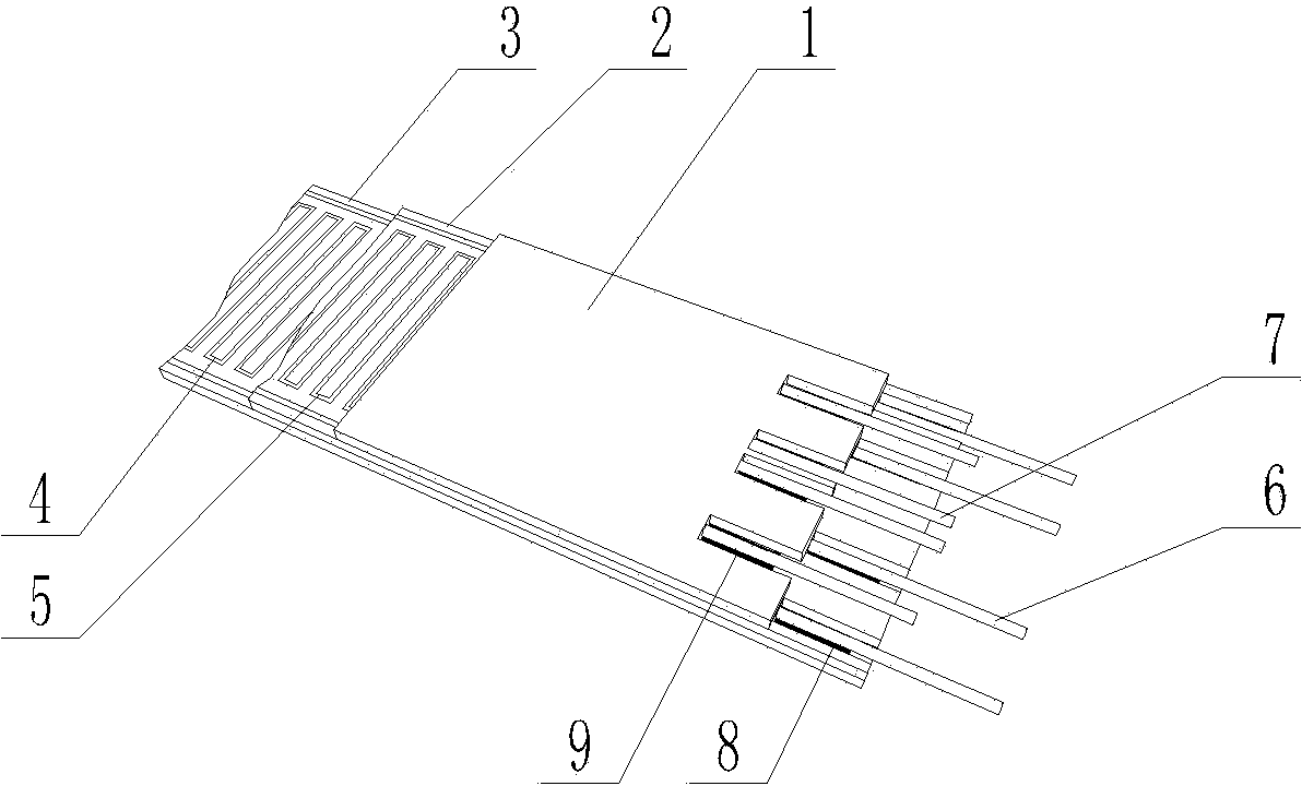
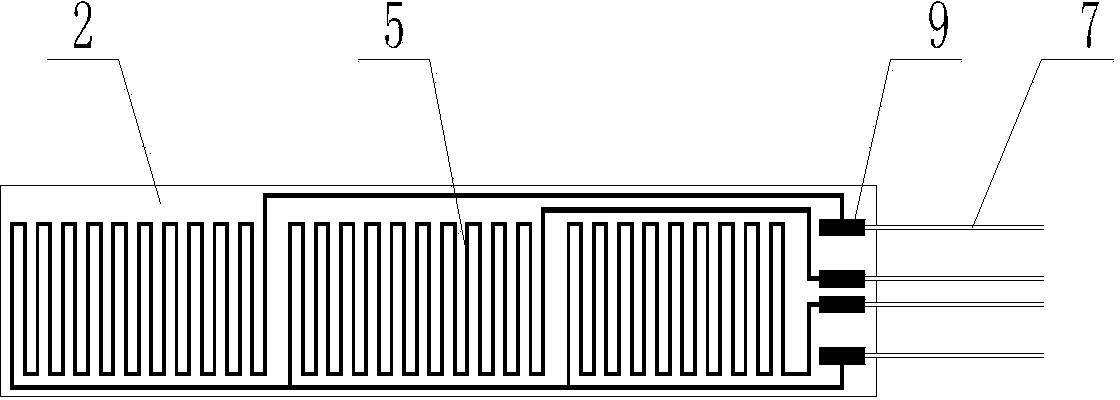
[0016] Figure 1 to Figure 4 The first specific embodiment of the pad structure of a ceramic heating sheet with temperature control is given in the present invention, which is composed of an upper ceramic sheet 1, a middle ceramic sheet 2, a lower ceramic sheet 3, a heating resistor 4, a temperature control Resistor 5, heating lead wire 6, temperature control lead wire 7, heating resistance pad 8, temperature control resistance pad 9 are composed of a plate structure, this embodiment is a flat plate structure, upper ceramic sheet 1, middle ceramic sheet 2, lower ceramic sheet The ceramic sheets 3 are stacked sequentially, there are three heating resistors 4 , and there are three temperature control resistors 5 correspondingly. The heating resistor 4 is printed on the surface of the lower ceramic sheet 3, and after lamination, it is bonded to the surface of the middle ceramic sheet 2, the heating resistor pad 8 is printed on the surface of the lower ceramic sheet 3, and the tem...


PUM


Abstract

The invention discloses a bonding pad structure of a ceramic heating piece with temperature control. The bonding pad structure of the ceramic heating piece with the temperature control is of a plate structure formed by an upper ceramic piece (1), a middle ceramic piece (2), a lower ceramic piece (3), heating resistors (4), temperature control resistors (5), heating leads (6), temperature control leads (7), heating resistance bonding pads (8) and temperature control resistance bonding pads (9), wherein the ceramic pieces are stacked in sequence, the multiple heating resistors (4) and the multiple temperature control resistors (5) are provided correspondingly, the heating resistors (4) and the temperature control resistors (5) are located on different planes, the heating resistance bonding pads (8) and the temperature control resistance bonding pads (9) are also located on different planes and are located on the same side of the ceramic heating pieces, and the area where the heating resistance bonding pads (8) located and the area where the temperature control resistance bonding pads (9) located are staggered in a stair shape. The density of the welding pads and the density of lead arrangement are reduced to a large extent, printing and lead welding operation is easy, the rate of finished products is ensured, and manufacturing cost is lowered.

Description

technical field [0001] The invention relates to a pad structure of a ceramic heating sheet, in particular to a pad structure of a ceramic heating sheet with temperature control, and belongs to the technical field of electric heating. Background technique [0002] Ceramic heating element is a new generation of high-efficiency, green and environmentally friendly heating device, which is widely used in various heater products such as industrial and agricultural technology, communication, medical treatment, and daily life. It is used to provide heat sources for heating components or directly as heating components. . At present, the ceramic heating element with temperature control on the domestic and foreign markets has a three-layer ceramic chip type or a double-layer ceramic chip type, and the welding pad is located at the end of one of the ceramic chips. , the currently used pad structure is to arrange pads on the surface of the end of the same layer of ceramic sheet, so th...

Claims


Application Information

Patent Timeline
Patent Type & Authority Applications(China)
IPC IPC(8): H05B3/28
Inventor 兰海邹琦张静余咏梅徐有琴
Owner FUJIAN MINHANG ELECTRONICS
Learn More