In-furnace handling device and heating furnace

A technology of a handling device and a heating furnace, which is applied in the field of heating furnaces, can solve the problems of increased water cooling loss, large water cooling equipment, etc., and achieves the effects of reducing the excavation depth, reducing the operating cost and reducing the cost.

Active Publication Date: 2017-07-11
CHUGAI RO CO LTD
View PDF4 Cites 0 Cited by
  • Summary
  • Abstract
  • Description
  • Claims
  • Application Information

AI Technical Summary

Problems solved by technology

[0007] However, in the walking beam type furnace conveyance device, since each moving beam is installed so as to extend substantially the entire length of the furnace along the conveying direction of the object as described above, in order to Water-cooling is carried out on each of the moving beams extending approximately the entire length of the beam, requiring large-scale water-cooling equipment, and there are also problems such as increased water-cooling loss.

Method used


Image

  • In-furnace handling device and heating furnace
  • In-furnace handling device and heating furnace
  • In-furnace handling device and heating furnace

Examples


Embodiment Construction

[0045] Hereinafter, an in-furnace conveying device and a heating furnace provided with the in-furnace conveying device according to an embodiment of the present invention will be specifically described with reference to the drawings. In addition, the in-furnace conveyance apparatus and heating furnace of this invention are not limited to the in-furnace conveyance apparatus and heating furnace shown in the following embodiment, It can change suitably within the range which does not change the inventive idea, and can implement.

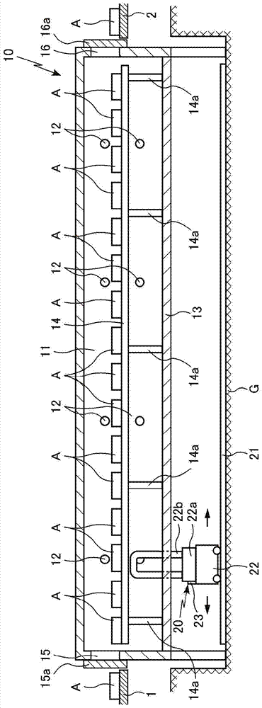
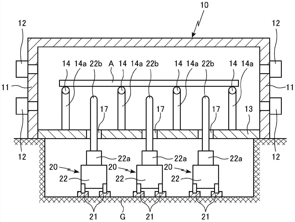
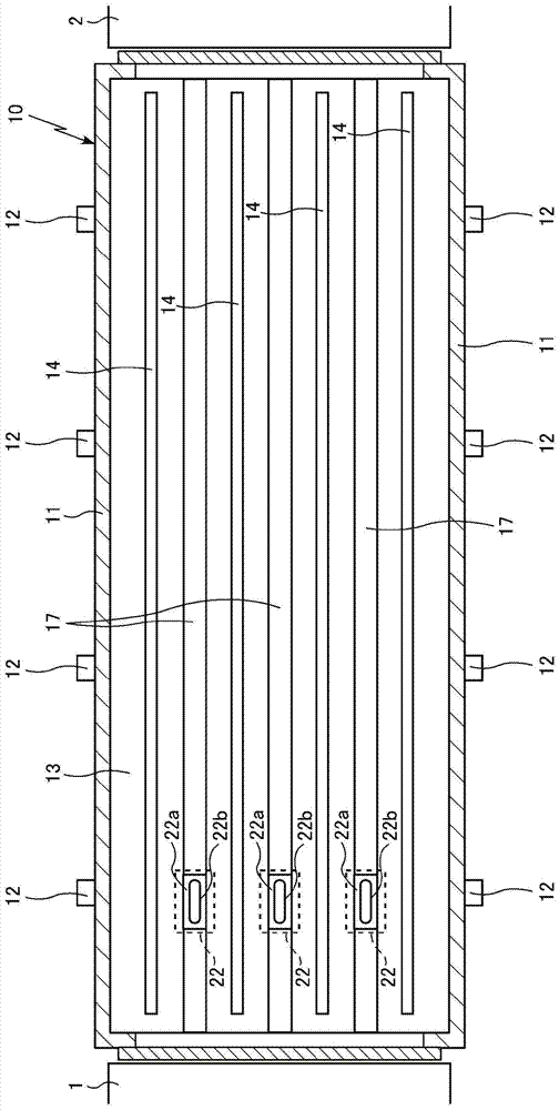
[0046] In the heating furnace 10 of the present embodiment, as Figure 1 ~ Figure 3 As shown, a plurality of combustion devices 12 are provided on its side wall 11, and support members 14a are erected on the hearth 13 of the heating furnace 10 at a required interval in the conveying direction of the object A to be processed. The member 14a is provided with a fixed beam 14 along the conveying direction of the processed object A, so that a plurality of su...


PUM


Abstract

An in-furnace conveying device, when using the in-furnace conveying device to sequentially move the processed objects on the fixed beam above the hearth of the heating furnace, the equipment is very simple compared with the walking beam type in-furnace conveying device Moreover, it is low cost and can be easily maintained. A plurality of fixed beams (14) along the conveying direction of the object to be processed (A) in the heating furnace (10) are arranged above the hearth (13), and in the width direction of the heating furnace in the manner of penetrating the hearth, A plurality of conveying guide grooves (17) along the conveying direction of the object to be processed are provided on the top, and a lifting and holding part protruding upward and lifting through the conveying guide grooves is provided on the cart (22) traveling along the conveying guide grooves. (22b) Raise the elevating and holding part to hold the object to be processed fixed on the fixed beam on the elevating and holding part, and at the same time make the trolley advance to a predetermined position in the conveying direction to make the object to be processed held on the fixed beam Move in turn.

Description

technical field [0001] The present invention relates to an in-furnace conveying device for conveying objects to be processed in a furnace and a heating furnace including the in-furnace conveying device. In particular, when using the in-furnace conveying device to convey the object to be processed in the furnace, compared with the existing walking beam-type furnace conveying device, the equipment is very simple, can greatly reduce the overall cost, and can also easily maintenance, etc., wherein, in the above-mentioned existing walking beam type furnace conveying device, when the object to be processed is moved along the conveying direction on the fixed beam arranged above the hearth to carry out conveying, use The moving frame reciprocates a moving beam installed along the conveying direction of the object in the up-down direction and the conveying direction to perform a stepping operation, and the moving beam sequentially moves the object on the fixed beam for conveyance. Ba...

Claims


Application Information

Patent Timeline
Patent Type & Authority Patents(China)
IPC IPC(8): C21D1/00C21D9/00F27B9/26F27B9/38F27B9/39F27D3/12
CPCC21D1/00C21D9/00F27B9/26F27B9/38F27B9/39F27D3/12
Inventor 山本俊辅
Owner CHUGAI RO CO LTD
Why Eureka
Try Eureka