
Detachable wardrobe

A detachable wardrobe technology, applied in wardrobes, detachable cabinets, cabinets, etc., can solve problems such as inconvenient adjustment and complicated cabinet structure

Inactive Publication Date: 2014-06-25
周波
View PDF4 Cites 7 Cited by
  • Summary
  • Abstract
  • Description
  • Claims
  • Application Information

AI Technical Summary

Problems solved by technology

There are also cabinets with the help of iron frames as the skeleton, and various boards are installed in the space between the iron frames to realize the disassembly structure, but the structure of this iron frame type cabinet is too complicated, and it is only a traditional wood cabinet. A Variation of the Frame Structure
But in any case, the structure of these wardrobes all follow the traditional structure concept, not only including the base plate, top plate, side plate and cabinet door, but also fixing the laminates or clothes rails on the left and right side plates or the left and right vertical partitions Between, the vertical partition board is fixedly arranged between the top board and the bottom board, so that once the use space in the wardrobe is finalized, it is not convenient to flexibly adjust according to the needs of use, such as adjusting height, width, etc.

Method used


Image

  • Detachable wardrobe
  • Detachable wardrobe
  • Detachable wardrobe

Examples


Embodiment Construction

[0057] The structure of the detachable wardrobe product applying the present invention will be further described below in conjunction with the accompanying drawings.

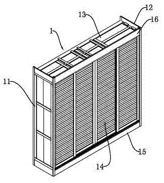
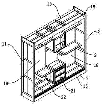
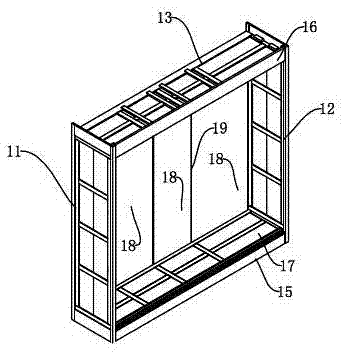
[0058] Such as figure 1 , figure 2 with image 3 As shown, a detachable wardrobe 1 includes a left side panel 11, a right side panel 12, a top panel 13, a door panel 14, an upper fascia board 16, a lower fascia board 15, a bottom board 17, and a back board 18; The board 11 and the right side board 12 are respectively connected to the left and right ends of the bottom board 17, the top board 13 is erected on the top of the left side board 11 and the right side board 12, and the upper lintel board 16 is arranged on the top board 13, the lower fascia board 15 is arranged at the front edge of the bottom board 17 and blocks the bottom space below the bottom board 17, and the door board 14 is arranged on the left side board 11, In the doorway of the frame formed by the right side panel 12 and the bottom panel 17 ,...


PUM


Abstract

The invention relates to a detachable wardrobe which comprises a back plate, a bottom plate and a metal bottom frame system. The metal bottom frame system comprises at least two L-shaped hollow metal bottom frames arranged in a left and right spacing mode and side by side. The metal bottom frames comprise vertical stand columns and horizontal columns, wherein the vertical stand columns and the horizontal columns are connected into one. The inner side walls of the vertical stand columns are provided with first clamping holes arranged at intervals. A plurality of the first clamping holes are formed in the extending direction of the vertical stand columns. The bottom plate is arranged on the horizontal columns, and the back plate is vertically arranged on the vertical stand columns. The first clamping holes are exposed out of the two sides of the back plate. The bottom plate and the horizontal columns are connected through a stud or the left and right metal bottom frames are connected through a transverse connecting rod. Accordingly, the wardrobe can be disassembled and assembled on site, the whole stability of the wardrobe is improved by means of the metal frames, the metal frames bear the main weight of the wardrobe, the number of installation holes in the side wooden plate or the bottom wooden plate or the top wooden plate can be reduced, and the thickness, namely, the adopted amount of the side plate or the bottom plate or the top plate can be reduced.

Description

technical field [0001] The invention relates to a detachable wardrobe, in particular to a detachable wardrobe which can realize multifunctional combination and is convenient for production organization and on-site installation. Background technique [0002] Existing storage cabinets such as wardrobes mainly include fixed cabinets made by carpenters on the home site according to their production methods, and the top board, side boards and bottom boards of the cabinet are all positioned on the wall or only door leaves are set at all. The walls are used as the side walls of the wardrobe; there are also pre-assembled cabinets that are placed in the room directly after pre-assembly in the factory, and there is also a cabinet that is assembled on-site in the home after only the various components of the wardrobe are produced in the factory. Detachable wardrobe. For disassembled wardrobes, especially wooden disassembled wardrobes, the bottom plate, top plate, side panels, laminate...

Claims


Application Information

Patent Timeline
Patent Type & Authority Applications(China)
IPC IPC(8): A47B47/00A47B61/00A47B57/20A47B96/00
Inventor 周波
Owner 周波
Learn More