A connection structure and construction method of a prefabricated rail top air duct and a structural slab

A rail-top air duct and connecting structure technology, applied in the field of rail transit, can solve the problems of difficult to guarantee construction quality, narrow rail-top air duct space, easy to leave quality hidden dangers, etc., achieving fast construction speed, saving construction time and cost, The effect of a reliable connection

Active Publication Date: 2021-12-24
CHINA RAILWAY SIYUAN SURVEY & DESIGN GRP
View PDF1 Cites 0 Cited by
  • Summary
  • Abstract
  • Description
  • Claims
  • Application Information

AI Technical Summary

Problems solved by technology

During the later construction of the rail top air duct, the scaffolding for erecting the structural slab has been removed, and the scaffolding and formwork need to be erected again, which is time-consuming, laborious and expensive
[0005] (2) The air duct on the rail top is suspended below the structural slab by using the steel bars reserved in the structural slab. The space of the air duct on the rail top is narrow, and there are great difficulties in tying steel bars and pouring concrete. It is difficult to guarantee the construction quality, and it is easy to leave quality risks
[0006] (3) On-site pouring of the rail top air duct is time-consuming, laborious and expensive

Method used


Image

  • A connection structure and construction method of a prefabricated rail top air duct and a structural slab
  • A connection structure and construction method of a prefabricated rail top air duct and a structural slab
  • A connection structure and construction method of a prefabricated rail top air duct and a structural slab

Examples


Embodiment 1

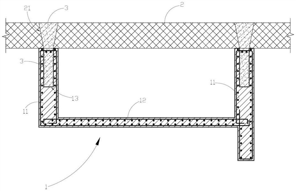
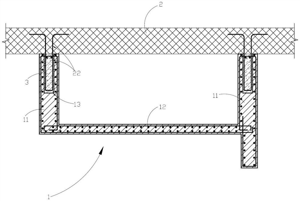
[0031] Such as Figure 1-Figure 3 , the embodiment of the present invention provides a prefabricated rail roof air duct, including a plurality of air duct units 1 spliced ​​in sequence along the longitudinal direction of the air duct, each of the air duct units 1 includes a bottom plate 12 and at least two connected to the bottom plate 12 Each side plate 11, in each of the air duct units 1, at least one of the side plates 11 is provided with a pouring groove 13 for pouring concrete 3 on the top.

[0032] The above-mentioned bottom plate 12 is connected with at least two side plates 11 to form a groove structure, wherein the above-mentioned air duct unit 1 can adopt the structural shape of the area where the screen door is hung below, that is, it has a vertical wall, and the bottom plate 12 is connected to the middle of the side plate 11; In other embodiments, it can also be used in a structure without a vertical wall, and the bottom plate 12 is connected to the bottom end of t...

Embodiment 2

[0044] Such as Figure 1-Figure 5 , the embodiment of the present invention provides a connection structure between the rail top air duct and the structural plate 2, including the rail top air duct and the structural plate 2, the rail top air duct includes a plurality of air duct units 1 sequentially spliced ​​along the longitudinal direction of the air duct, each of which The air duct units 1 are all prefabricated structures, the top of each of the air duct units 1 is provided with pouring grooves 13, the structural plate 2 is provided with a plurality of pouring holes 21, and each of the pouring holes 21 is connected with one of the pouring holes. The pouring grooves 13 are connected, and each of the air duct units 1 is solidified on the bottom of the structural plate 2 through the cast-in-place concrete 3 poured in each of the pouring holes 21 and each of the pouring grooves 13 . Wherein, the rail top air duct preferably adopts the prefabricated rail top air duct provided i...


PUM


Abstract

The invention relates to a connection structure between a prefabricated rail top air duct and a structural plate and a construction method thereof. The connection structure includes a rail top air duct and a structural plate. There are pouring grooves on the top of the air duct unit, and a plurality of pouring holes are opened on the structural plate, and each pouring hole is connected to one of the pouring grooves. Concrete is cemented to the bottom of the structural slab. By setting pouring grooves on the top of the side slabs of the air duct unit and setting pouring holes on the structural slab and pouring concrete in place, the reliable connection between the air duct unit and the structural slab can be realized without scaffolding, formwork, etc., and the construction efficiency is high and effective Save construction time and cost; can significantly improve the stability and reliability of the installation structure of the rail top air duct; cast-in-place concrete can isolate the gap between the air duct unit and the structural plate, and improve the sealing of the rail top air duct.

Description

technical field [0001] The invention belongs to the technical field of rail transit, and in particular relates to a connection structure between a prefabricated rail top air duct and a structural plate and a construction method thereof. Background technique [0002] At present, most of the rail top air duct structures are constructed with cast-in-place reinforced concrete. The construction environment is poor, the process is complicated, and the speed is slow. The construction quality is difficult to guarantee due to various factors. At the same time, a lot of abandoned construction waste is generated during the construction process, which not only wastes resources but also pollutes the environment. [0003] Specifically, there are the following problems in the construction of cast-in-place rail top air duct: [0004] (1) The rail top air duct is generally located below the subway structural slab and above the track. It is a secondary structure of the station and needs to b...

Claims


Application Information

Patent Timeline
Patent Type & Authority Patents(China)
IPC IPC(8): E04F17/04
CPCE04F17/04
Inventor 徐军林汪国良朱丹林作忠王华兵付先进许俊超胡正波周兵余行张波
Owner CHINA RAILWAY SIYUAN SURVEY & DESIGN GRP
Why Eureka
Try Eureka