Pouring mold for outer barrel of dust collector

A technology for vacuum cleaners and outer barrels is applied in the field of casting molds for the production of vacuum cleaner outer barrels, which can solve problems affecting product quality, outer barrel quality problems, poor reliability, etc. good reliability

Inactive Publication Date: 2014-06-25
SUZHOU XINRONG FITNESS EQUIP
View PDF3 Cites 0 Cited by
  • Summary
  • Abstract
  • Description
  • Claims
  • Application Information

AI Technical Summary

Problems solved by technology

[0002] Vacuum cleaner is a common small household appliance in daily household. Its outer barrel is made of plastic parts, which are usually finished by plastic injection mould. The design of the mold structure directly affects the efficiency of mold core pulling and also has a great impact on the quality of the product. Although the current mold structure can successfully complete the core pulling, the efficiency is low and the poor reliability will easily lead to quality problems of the outer barrel

Method used


Image

  • Pouring mold for outer barrel of dust collector
  • Pouring mold for outer barrel of dust collector
  • Pouring mold for outer barrel of dust collector

Examples


Embodiment Construction

[0010] The specific implementation manner of the present invention will be described below in conjunction with the accompanying drawings.

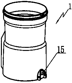
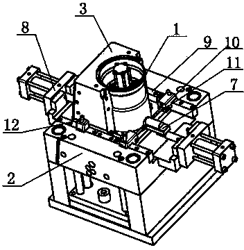
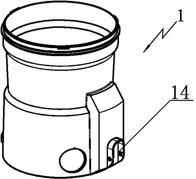
[0011] See Figure 1 to Figure 5 , the present invention comprises a lower mold base 2, the lower mold base 2 has a lower mold groove, the two sides of the lower mold groove are fixedly connected with slide rails 9, the bottom surface of the lower mold groove has a lower mold hole, and the lower mold groove A mold core 13 is installed in the mold hole, and the mold core 13 is used to generate the inner cavity of the product; the lower mold base 2 is fixedly connected with a bracket 5 at both ends of the lower mold groove, and a cylinder 8 is installed on the bracket 5, and the cylinder 8 The push rod is connected to the left mold base 4 and the right mold base 3 arranged in the lower mold groove, and the cylinder 8 can push and pull the left mold base 4 and the right mold holder 3 to slide along the slide rail 9 in the lower mold groove. ...


PUM


Abstract

The invention relates to a pouring mold for an outer barrel of a dust collector. The pouring mold comprises a lower mold base, wherein a lower mold groove is formed in the lower mold base and is fixedly connected with sliding rails; a lower mold hole is formed in the bottom surface of the lower mold groove; a mold core is arranged in the lower mold hole; brackets are fixedly connected with two ends, positioned on the lower mold groove, of the lower mold base; a cylinder is arranged on each bracket; push rods of the cylinders are connected with a left mold base and a right mold base which are arranged in the lower mold groove; the opposite side walls of the left mold base and the right mold base are arc-shaped; pouring gates are arranged at the tops of the left mold base and the right mold base; a gap is formed between each of the opposite side walls of the left mold base and the right mold base and the mold core, and is communicated with the corresponding pouring gate; sliding holes are formed in the side walls, positioned on the sliding rails, of the left mold base and the right mold base; core pulling blocks are positioned in the sliding holes and are supported on the sliding rails; a pull rod is arranged aslope on each core pulling block; a T-shaped groove is formed in one end part of each core pulling block; a pulling pin is vertically arranged in each T-shaped groove; mold pins are arranged in the left mold base and the right mold base along the parallel direction of the sliding rails. The pouring mold for the outer barrel of the dust collector is simple in structure, high in core pulling efficiency and high in reliability; the product quality is easily guaranteed.

Description

technical field [0001] The invention relates to the technical field of moulds, in particular to a casting mold for producing an outer tub of a vacuum cleaner. Background technique [0002] Vacuum cleaners are common small household appliances in daily household. The outer barrel is made of plastic parts, which are usually finished by injection molding of plastic injection molds. The design of the mold structure directly affects the efficiency of core pulling of the mold and also has a great impact on the quality of the product. Although the current mold structure can successfully complete the core pulling, the efficiency is low and the poor reliability will easily lead to quality problems of the outer barrel. Contents of the invention [0003] The applicant improves on the above-mentioned shortcomings in the prior art, and provides a vacuum cleaner outer tub casting mold, which has a simple structure, high core-pulling efficiency, good reliability and easy to ensure produc...

Claims


Application Information

Patent Timeline
Patent Type & Authority Applications(China)
IPC IPC(8): B29C45/26B29C45/33
CPCB29C45/26B29C45/33
Inventor 钱浩杰
Owner SUZHOU XINRONG FITNESS EQUIP
Why Eureka
Try Eureka