Stopping brake system of trailer used under coal mine shaft

A technology of parking brake and parking brake valve, applied in the direction of hydraulic brake transmission device, etc., to achieve the effect of improving parking braking force and increasing reliability

Active Publication Date: 2014-06-25
CHANGZHOU DEV & MFR CENT
View PDF6 Cites 19 Cited by
  • Summary
  • Abstract
  • Description
  • Claims
  • Application Information

AI Technical Summary

Problems solved by technology

However, it cannot be realized that the trailer also has bra

Method used


Image

  • Stopping brake system of trailer used under coal mine shaft

Examples


Embodiment 1

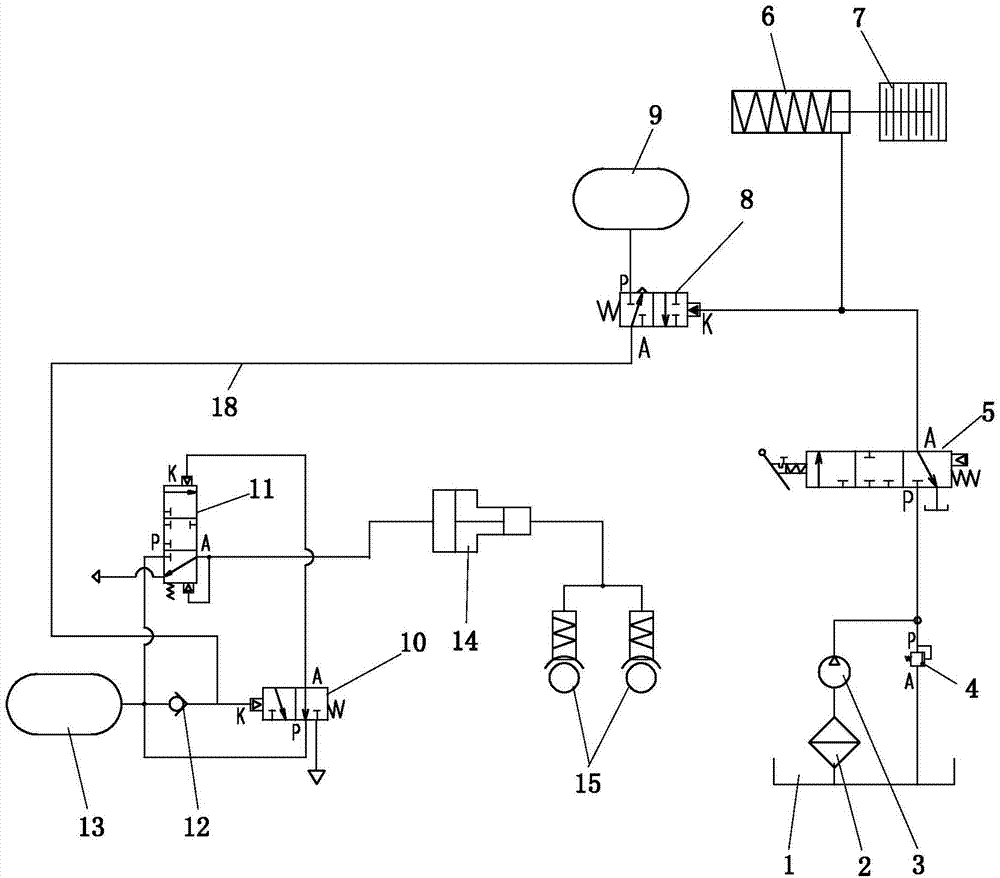
[0009] see figure 1 , The present invention includes oil tank 1, filter 2, hydraulic pump 3, safety valve 4, tractor parking brake valve 5, tractor parking hydraulic cylinder 6, tractor parking brake 7, hydraulic control air valve 8, first air bag 9. Air control valve 10, relay valve 11, one-way valve 12, second air bag 13, booster 14, trailer brake 15.

[0010] The oil inlet of the hydraulic pump 3 is connected to the oil tank 1 through the filter 2, the oil outlet of the hydraulic pump 3 is connected to the oil inlet P of the tractor parking brake valve 5, and the oil outlet of the tractor parking brake valve 5 Port A is connected to the control port K of the tractor parking hydraulic cylinder 6 and the hydraulic control air valve 8 through two oil channels. The tractor parking hydraulic cylinder 6 controls the tractor parking brake 7 to act. The first air bag 9 is connected to the air inlet P of the hydraulic control air valve 8, and the air outlet A of the hydraulic control ...


PUM


Abstract

A stopping brake system of a trailer used under a coal mine shaft comprises an oil tank, a filter, a hydraulic pump, a traction vehicle stopping brake valve, a traction vehicle stopping hydraulic cylinder, a traction vehicle stopping brake, a hydraulic control air valve, a first air bag, a pneumatic control valve, a relay valve, a one-way valve, a second air bag, an assistor and a trailer brake. The stopping brake system of the trailer used under the coal mine shaft enables the trailer to be braked as well when a traction vehicle is stopped and braked, largely improves the stopping and braking force, and improves the reliability when the vehicle is stopped and braked on a slope.

Description

Technical field [0001] The invention relates to a parking brake system for a trailer used in a coal mine. Background technique [0002] Trailers for underground coal mines include tractors and trailers. According to coal mine safety regulations, all vehicles in coal mines need to be equipped with a working brake system, an emergency brake system and a parking brake system. Usually, emergency brake and parking brake are a set of brake systems. At present, the trailer used in underground coal mines can realize the trailer braking when the tractor is braking. However, it cannot be realized that the trailer also brakes during parking brake and emergency braking. Summary of the invention [0003] The purpose of the present invention is to provide a parking brake system for trailers used in underground coal mines in which the trailers are simultaneously braked when the tractor is parking brakes. [0004] In order to achieve the above objectives, the present invention adopts the followi...

Claims


Application Information

Patent Timeline
IPC IPC(8): B60T11/10
Inventor 刘开华马祥宁陈峰万中元管晓强
Owner CHANGZHOU DEV & MFR CENT
Why Eureka
Try Eureka